|
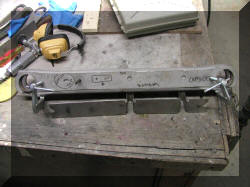 |
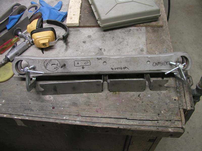
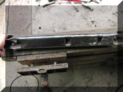
The first step is to locate the holes for sway bars.
I took a set of rear lower control arms that were to pitted for
resale. I cut the sides out and now use then for a jig to locate the
sway bar holes.If you look closely
or click the picture to enlarge it you will see that a drill is
being used to locate the jig in the correct location to mark the
sway bar bolt holes |
 |
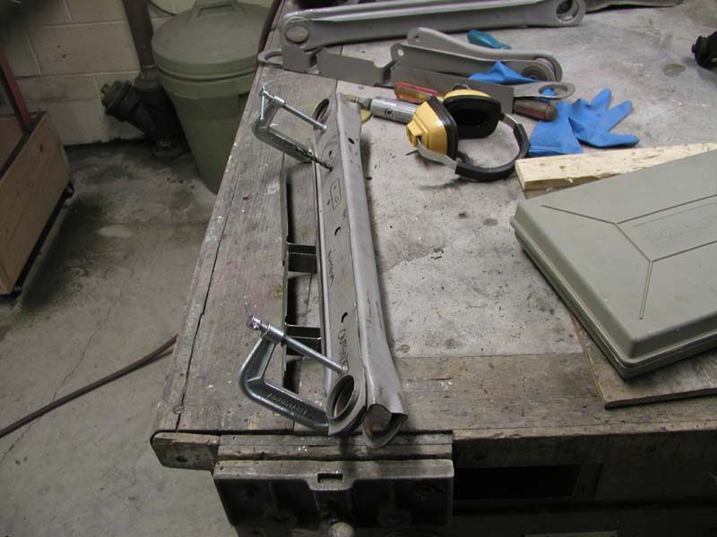
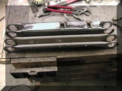
This is just another view of the "jig" clamped
in place with the drill locating the "jig" on the lower control arm
to be drilled for sway bar bolt holes.
A stepped drill bit is used for a nice clean
holes.
Both sides of the holes are ground so there
are no burrs.
|
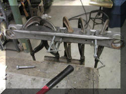 |
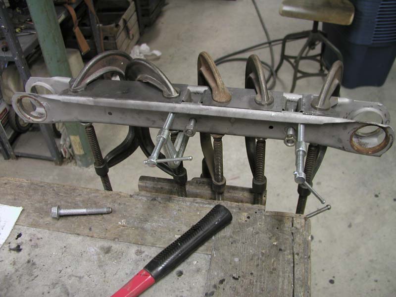
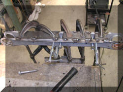
Many clamps are used to hold the insert in the
correct location.Bolts are inserted
through the sway bar bolt holes.
Clamps are placed on the sides to hold the
arm tight to the insert. |
 |
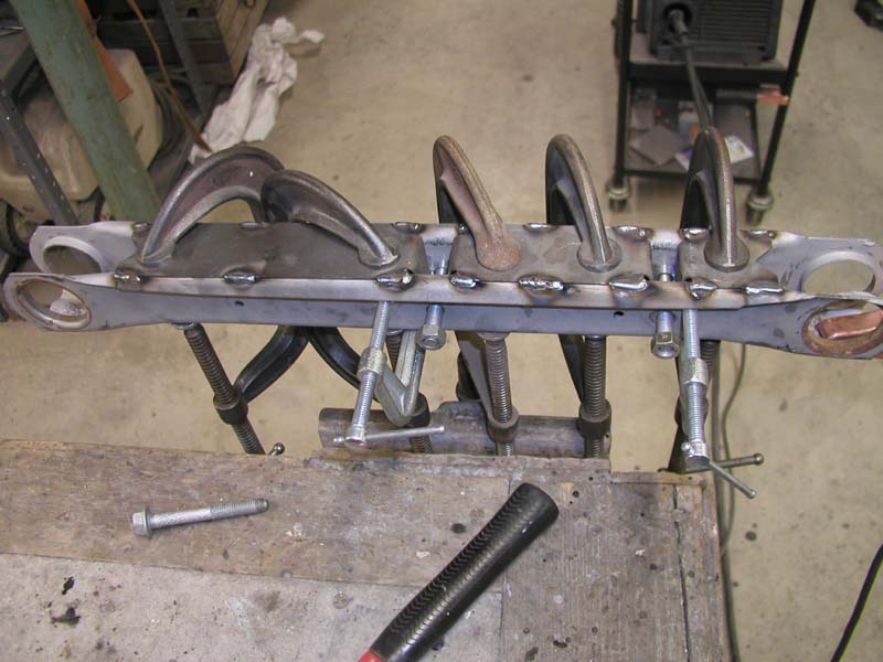
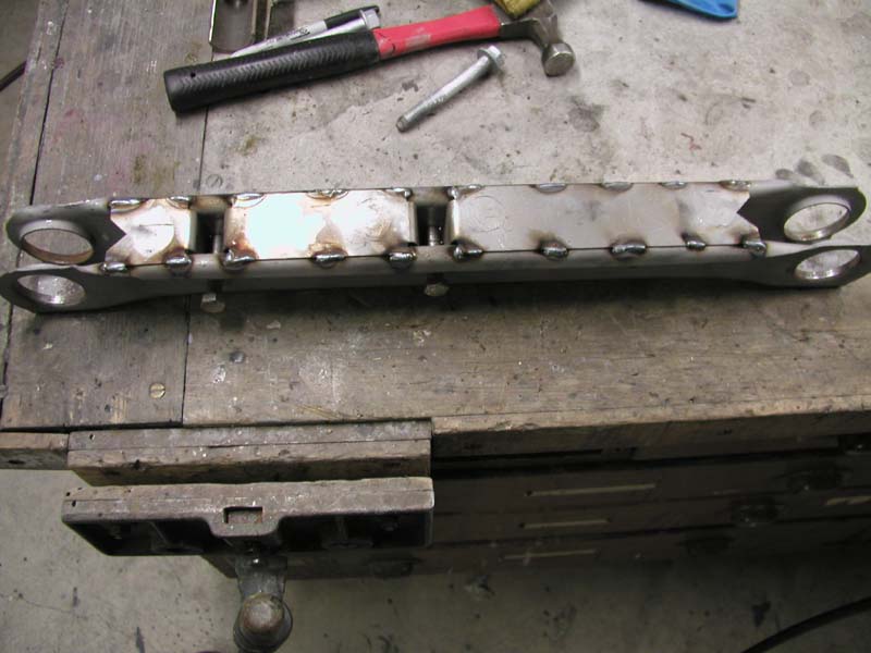
Small "stitch" welds are made in alternating
positions to avoid an warping of the arm |
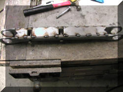 |
Additional "stitch" welds are made, once the
clamps have been removed to provide room to make those welds. |
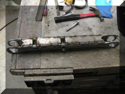 |
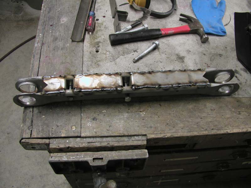
The "Stitch" welds are then all tied together
into one bead with additional "stitch" welds. All these small welds
are done to avoid any warping of the arm. Temperatures are kept as
low as possible and still get good penetration on the welds. |
 |
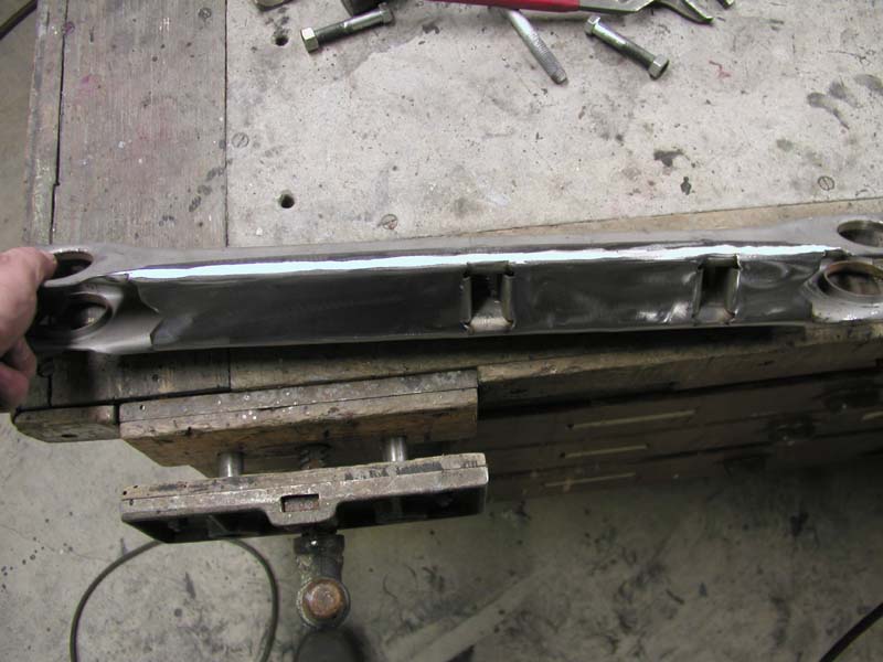
The weld bead is then ground to a smooth
finish, the entire length of the control arm. This gives the
appearance that the arm is all one piece. |
 |
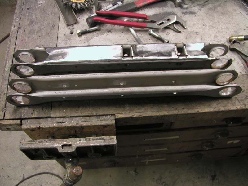
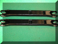
This is a before and after shot. |
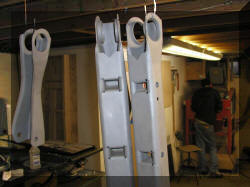 |
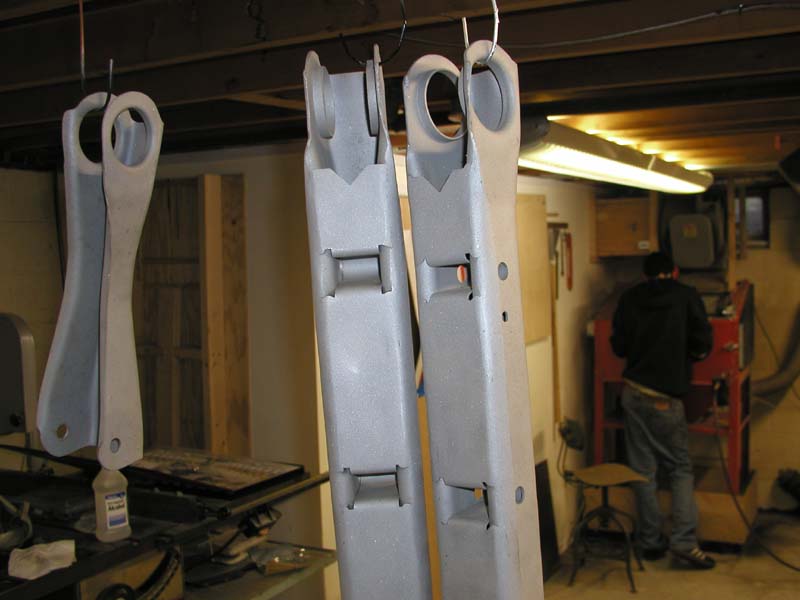
Ready for Powder Coat |
 |
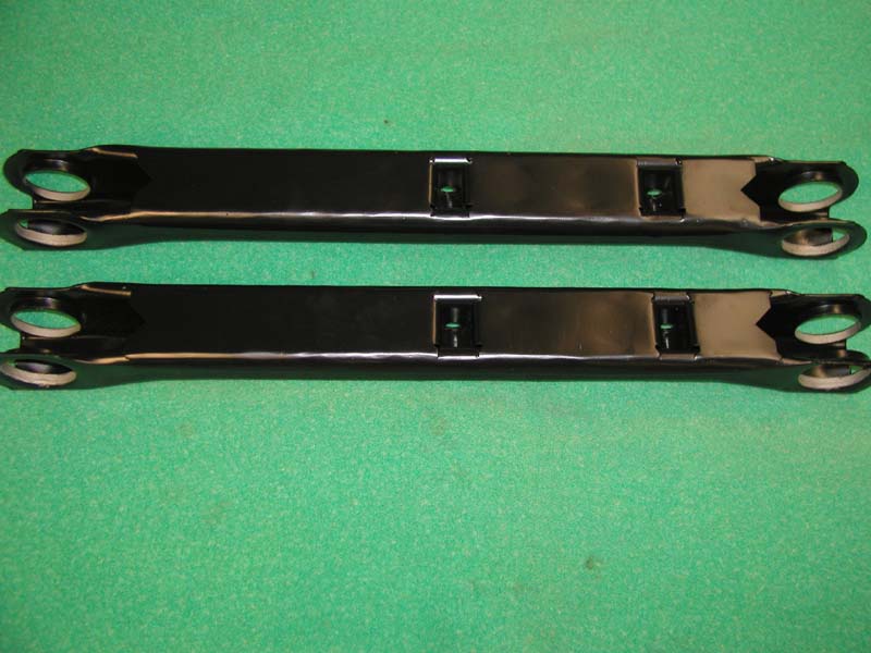
After Powder Coat |
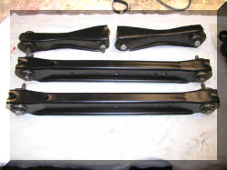 |
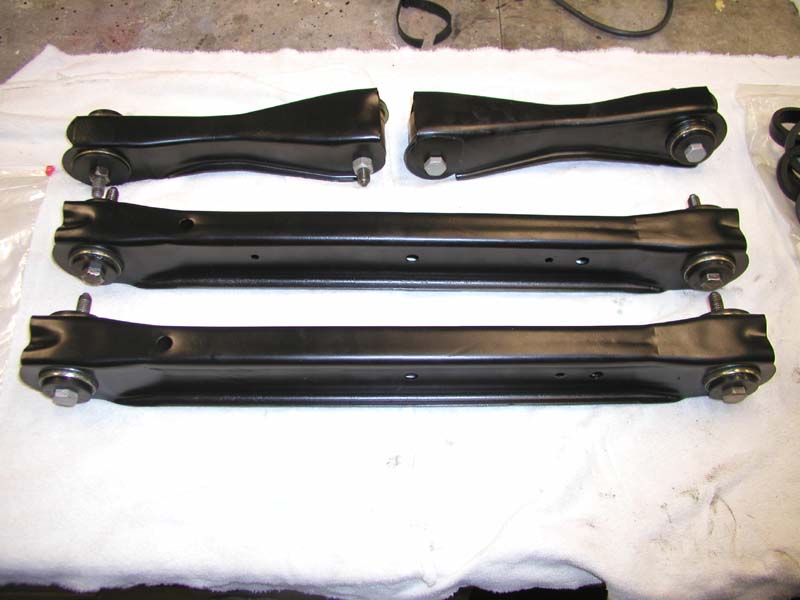
This is a set of upper rear control arms that were
converted to
12-bolt uppers and a set of lower boxed arms that were done for
a customer.
Bushings have been installed for the price
of the bushings, no charge for
the install.
Are you my next customer? I have a
money back guarantee (sorry, does not include shipping) |