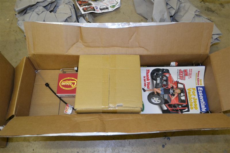
| More small tasks that need
to be completed before the Jeep can be driven down the
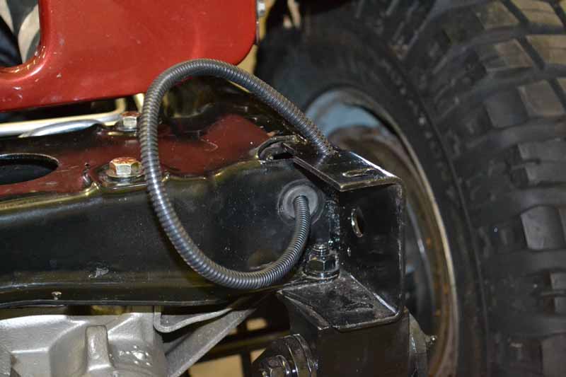
road, First up is installing longer flexible brake lines
needed because of the lift. This left to be done is the
rear one. That looks to be changeling as the lines are
rusted up. I may have to replace some of the steel line.
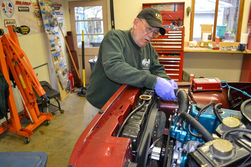
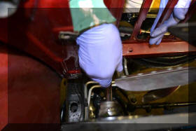
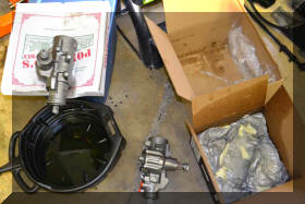
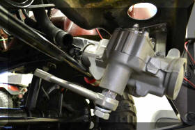
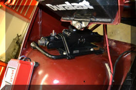
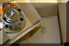
First up is to remove and replace
the Power steering gear box for the third time. The
first time was because the box had so much slop in it it
was unsafe to drive. The second was because the new box
was so tight that the steering wheel would not return
after making a corner, and the third time (this time)
was because the input shaft seal was leaking (found this
when I was fixing the leak out of the transfer case). |
 |
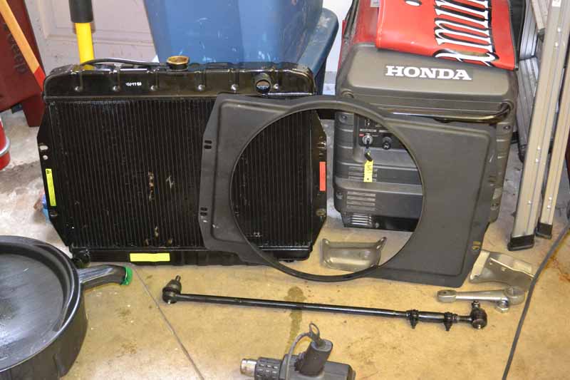
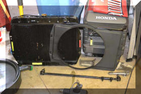
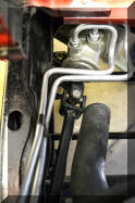
So Tom is once again over working
on pulling the steering box out. To pull it out the
radiator has to come out to get to the power steering
lines on the top of the box. |
 |
 |
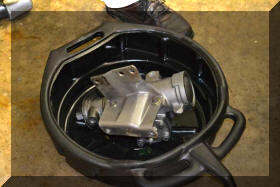 |
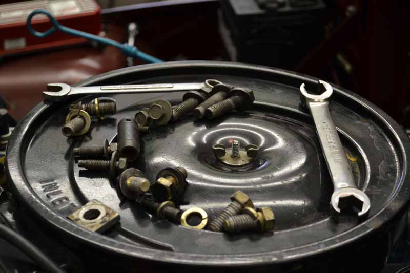
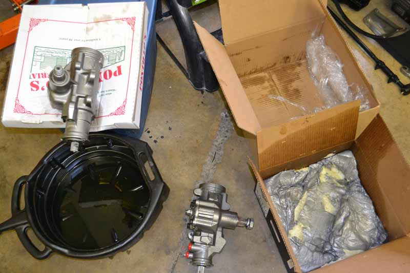
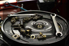
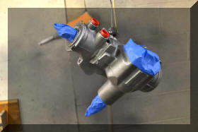
So the old box is out and we have
a new pile of parts to remember where they all have to
go back. |
 |
 |
 |
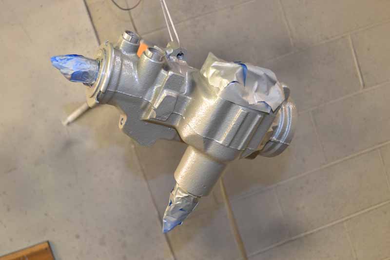
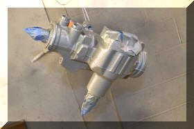
New box is here now all we have to
do is put it back and HOPE the third time is a charm. Of
course we can not leave well enough a lone, we have to
paint it up to look pretty. |
 |
 |
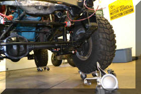 |
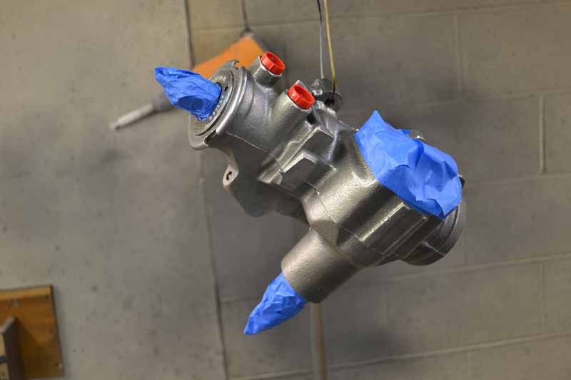
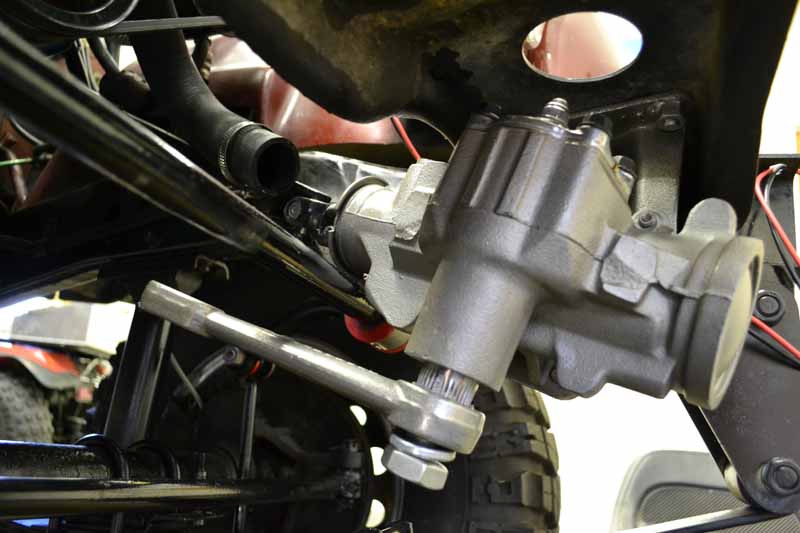
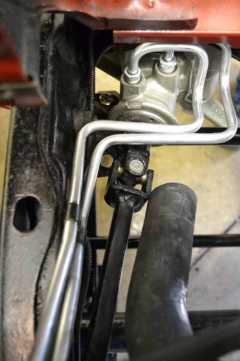
Now we are ready to reinstall the
gear box. Now the box is installed, ready to be primed.
Then the radiator can go back in. BUT first I want to
finish the wiring for the driving lights and do the drag
link sway. |
 |
 |
 |
 |
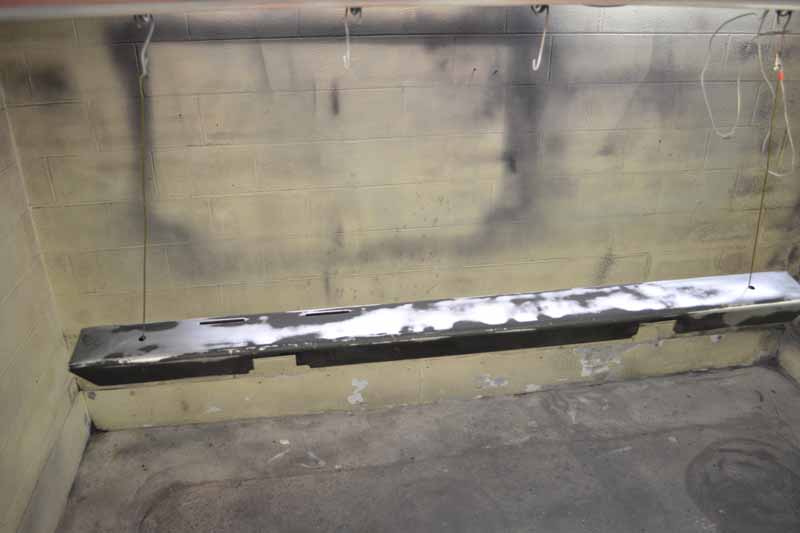
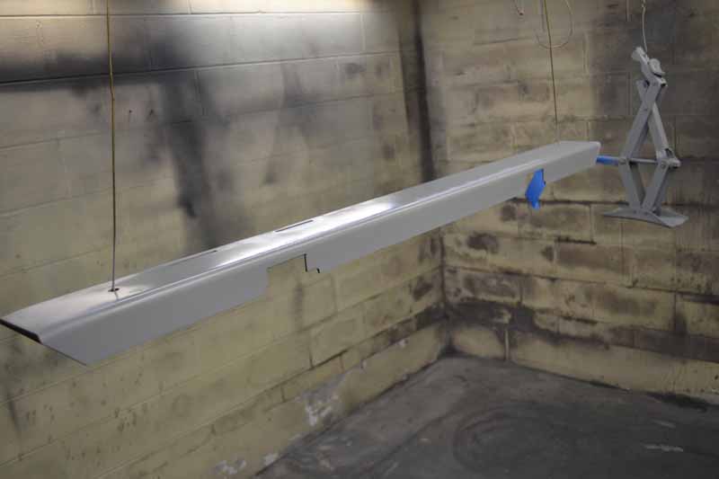
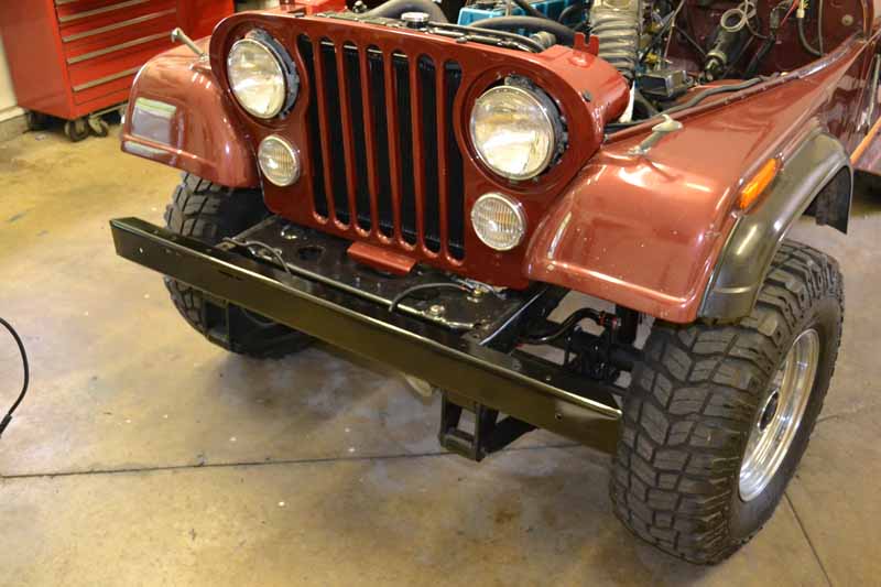
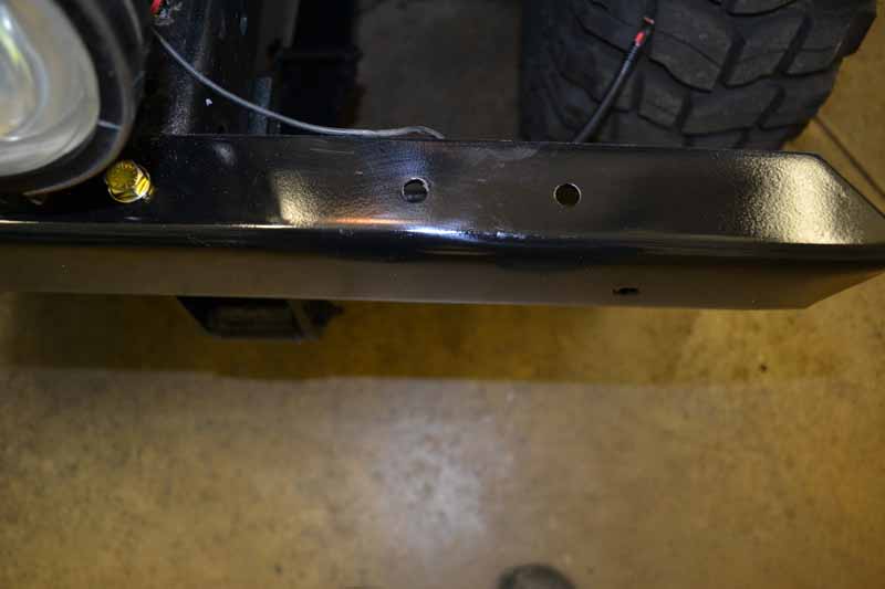
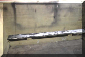
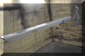
| Sanded
and painted the bumper, and jack. |
 |
 |
 |
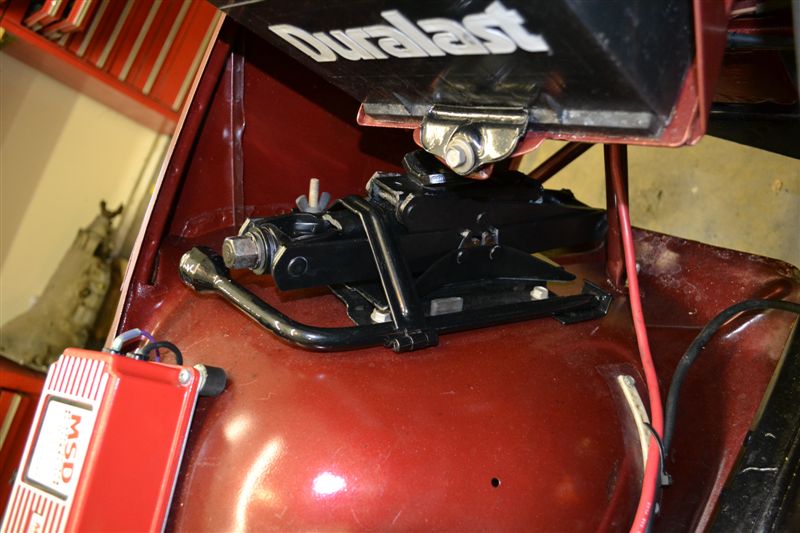
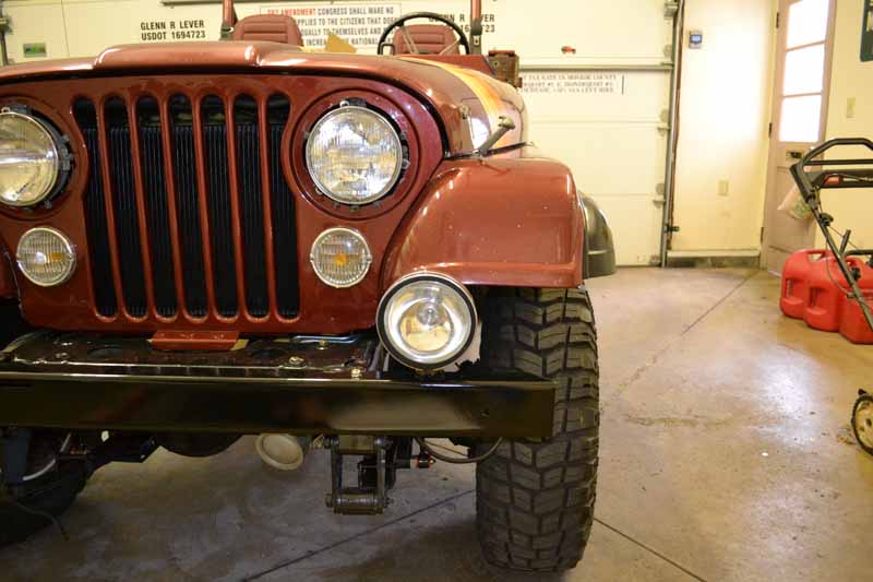
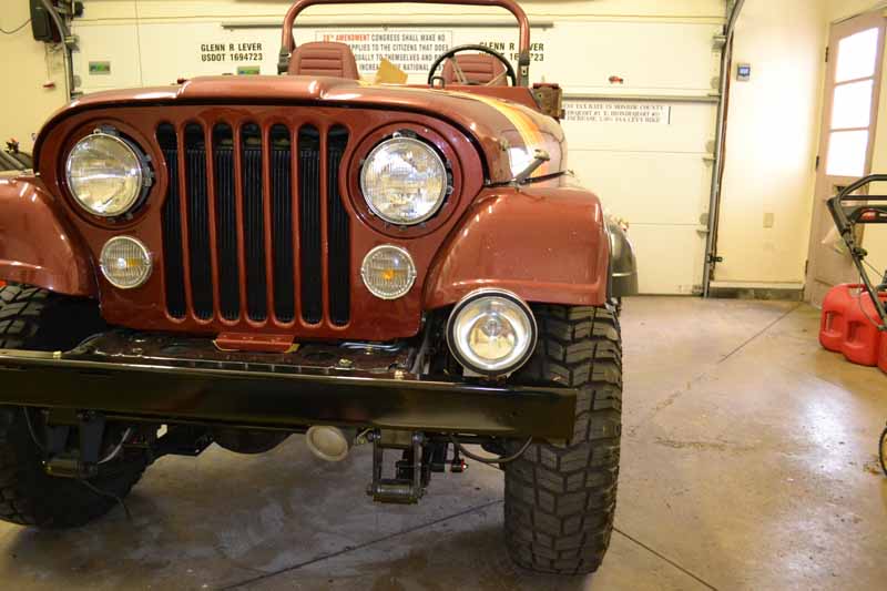
Installed the jack |
|
Installed the bumper |
 |
 |
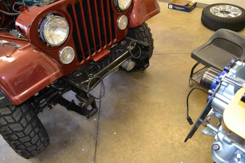
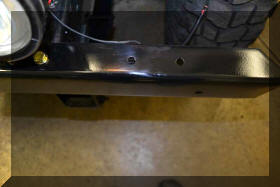
| So...
now to the driving lights. There are three logical
locations (three sets of holes that can be used). One is
at the intersection of the bumper and the frame. This
set is slightly recessed back from the edge of the
bumper. The other two sets are on the bumper below the
fender, one set further out from the center than the
other set. I leaning towards the outer set of holes on
the bumper as it is more centered on the bumper. The
hole at the intersection of the bumper and frame blocks
the turn signal. |
 |
 |
 |
 |
|
|
|
|
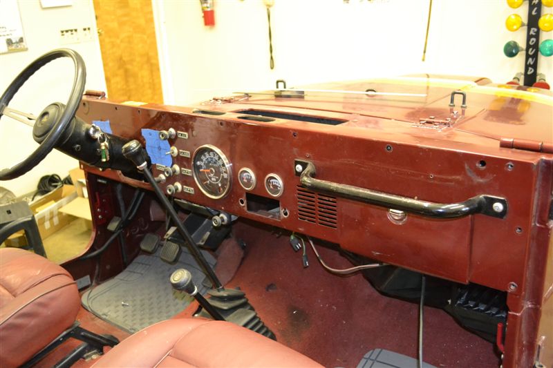
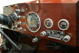
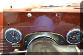
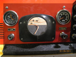
| Ok,
next project......THE DASH
If you look at the before and
after pictures below you might scratch your head and say
what is the big deal, read on. The dash really is a
bunch of other projects.
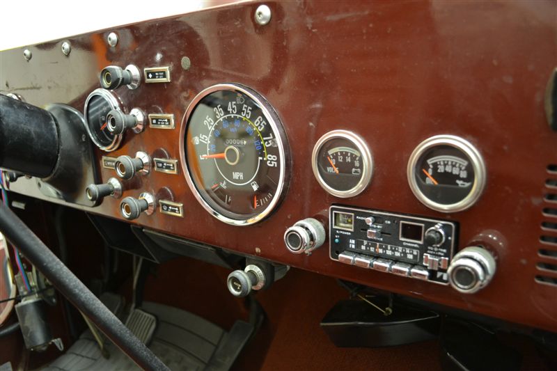
Install a Clock and a Tech that
were never installed on this Jeep but were an option
from the factory
Replace the Speedometer
Replace the AM/FM radio as the left channel does not
work and the tuning knob is broken off
Replace all the heater control cables. |
 |
 |
|
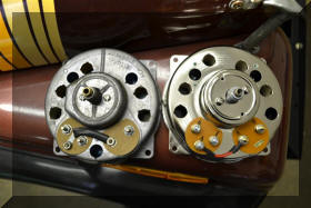
First dash project
project install a Tech and Clock on a dash that never
had them. There has been
a great deal of discussion on where the Clock and Tech
should be placed on the dash.
I have receive input that says
the Clock center lines should be 7 and 1/2 inches in
from the outside edge of the dash and 5 and 3/8 inches
up from the bottom edge. The tech should be 18 or 18 and
3/8 inches in from the outside edge and 5 and 3/8 inches
up from the bottom edge. The vertical center lines
should be centered on the lights and wiper knobs and the
horizontal center line should be centered on the AIR
(heat vent control). I laid out all those lines.
I do not know if my dash is
unique in some way but all those lines ended up in the
wrong spots.
None of the 7 and 1/2 inch, or
18, or 18 3/8 inch, vertical center lines in my Jeep
line up with the center of the wiper or light control
switches. The 7 and 1/2 inch vertical center line for
the clock ended up being 1/4 inch to the outside (away
from the steering wheel) of the vertical center line of
the light switch. The 18 inch vertical center line for
the Tech ended up being 3/16 inches to the inside
(toward the steering wheel) of the vertical center line
of the wiper switch, and the The 18 and 3/8 inch
vertical center line for the Tech ended up being 3/16
inches to the outside (away from the steering wheel) of
the vertical center line of the wiper switch.
In addition to that it has been
suggested that the holes for the Clock and Tech should
be 2 and 7/8 inches in diameter.
I purchased after market
insruments (clock and tech) the bezels are the same
diameter, but the bodies have different sizes. The clock
body measures 2 and 1/2 inches where the Tech body
measures 2 and 3/4 inches.
I found that if I used the
vertical center lines from the control knobs that the
instrument bezels would have touched the steering column
bezel.
If I drilled a 2 and 3/4 inch
hole for the clock on the 7 and 1/2 inch by 5 and 3/8
inch center lines the hole would have hit the right
upper edge of the left speaker in the dash.
So......
What I did was drill a 2 and
1/2 inch hole at 7 and 1/2 inches in and 5 and 3/8
inches up for the clock.
Using the gape between the
clock bezel and steering wheel bezel as a guide I found
that drilling a 2 and 3/4 inch hole 18 and 3/16 inches
in and 5 and 3/8 inches up gave me a even gape between
the clock and steering wheel bezel and the tach and the
steering wheel bezel.
Having done all that, an tried
to carefully measure everything I did not win. It turns
out that the 5 and 3/8 inch measurement from the bottom
of the dash does not put the instruments as high on the
dash as they should be (I say that based on pictures of
factory dashes with clocks and tech and the spacing the
tech has from the upper dash board pad retaining screw,
and that if the gauges were a little higher that the
clearances for the holes and stuff behind the dash would
not have been so tight.
|
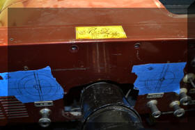 |
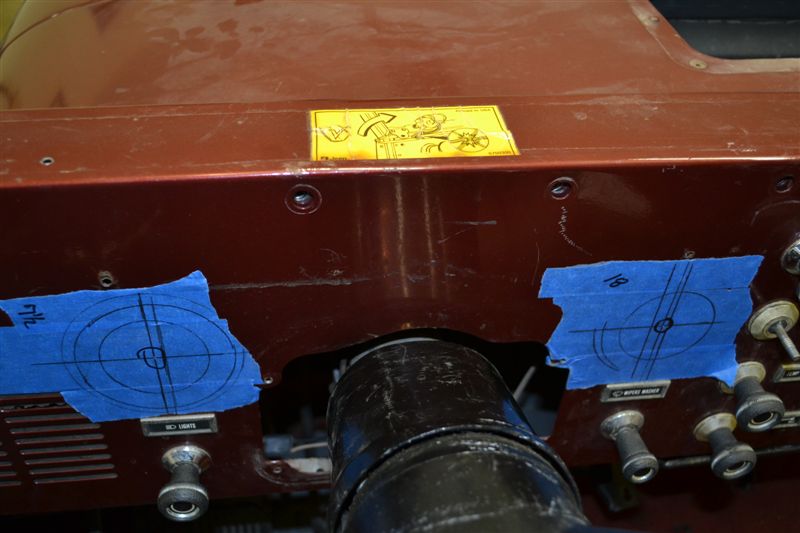
So here is a picture of all the
layout lines. There are center lines at different
measurements, out side bezel circles and hole circles |
 |
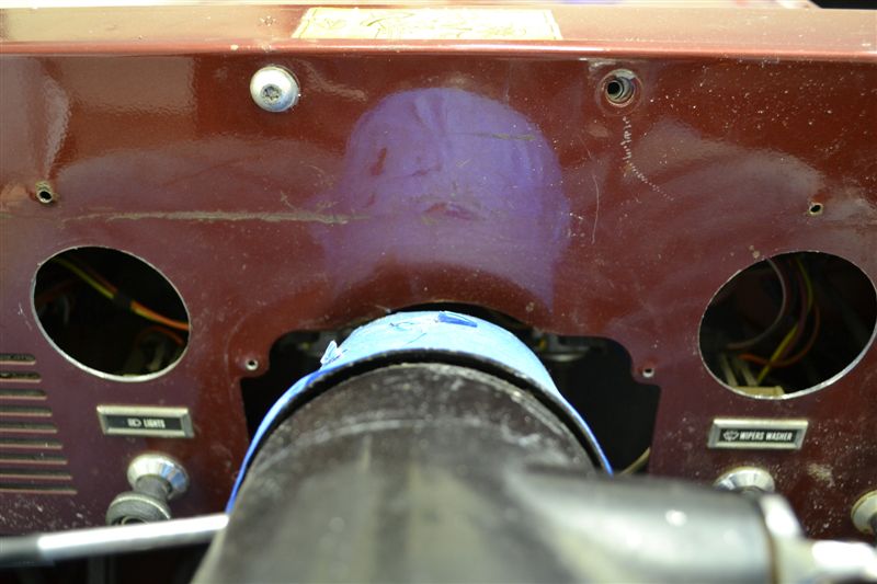
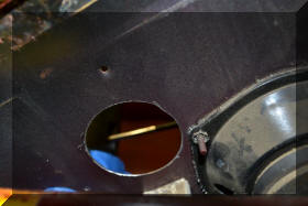
Here are the holes cut, note the
two different size holes |
 |
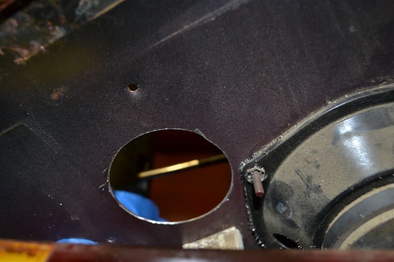
Placement of the clock hole is
VERY important as there is a large wiring harness behind
where the clock goes and the upper right speaker mount
for the left speaker is very close to where the clock
housing will come through. This picture is the back side
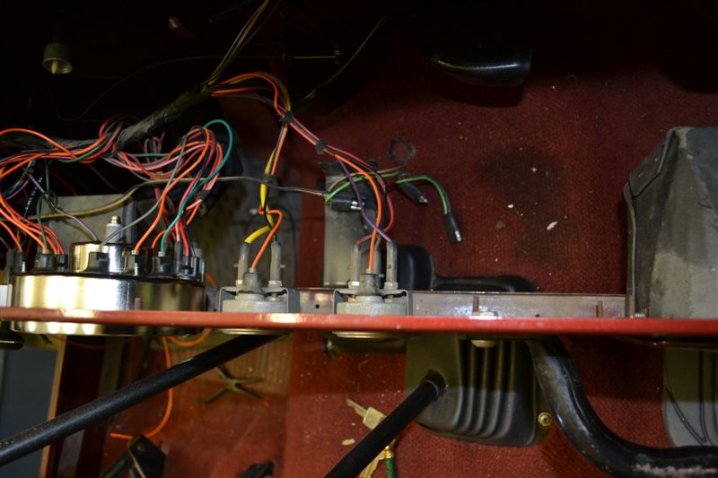
of the dash to show just how close it is |
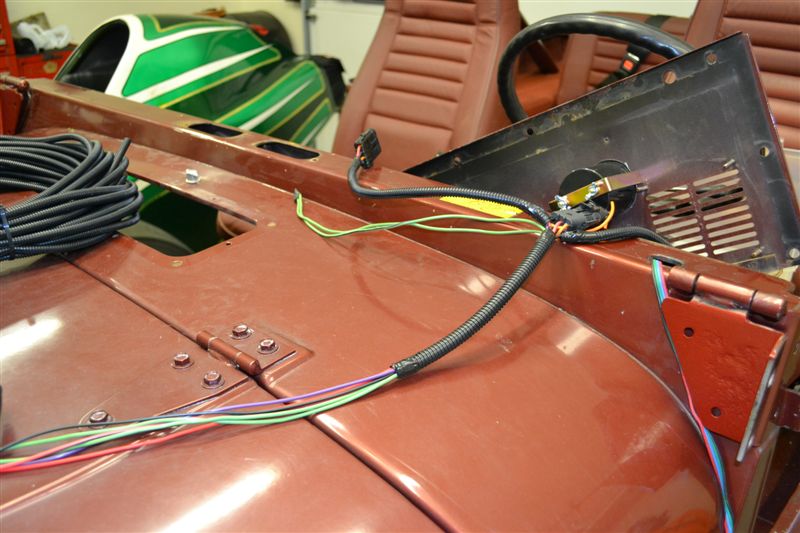
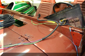
| I
created a small independent wiring harness for the tech
and clock. To have them work you need the following
feeds, ground, switched 12V unswitched 12 V, tech feed,
dash light feed. There is a spot in the fuse box for the
clock, labeled clock, for the switched feed I used the
radio feed from the fuse box as I also needed to get a
feed for the new radio to be installed. I ran a
dedicated
ground from my ground buss bar under the hood for the
whole dash, and picked up the dash light feed from the
headlight dash lable light. |
 |
 |
 |
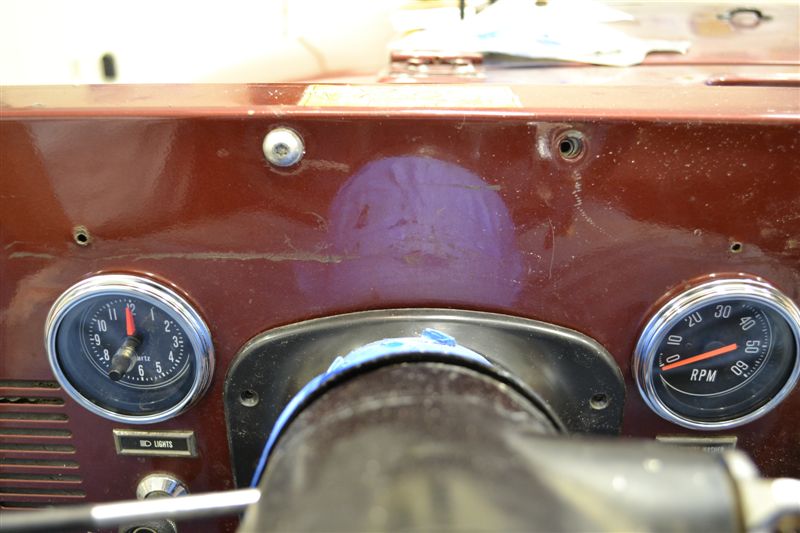
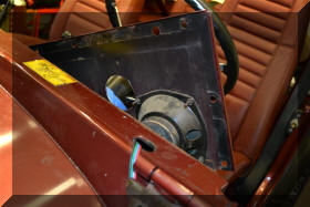
Here the instruments are inserted
into the holes. Note the gape between the instrument
bezels and the steering wheel bezel. Also note the
difference between the top of the Tech and the screw
hole for the dash pad screw in this picture and the
distance in the picture below. Also note that my picture
is taken from an upward angle as the steering wheel was
in the way and Keith's is taken straight on. |
 |
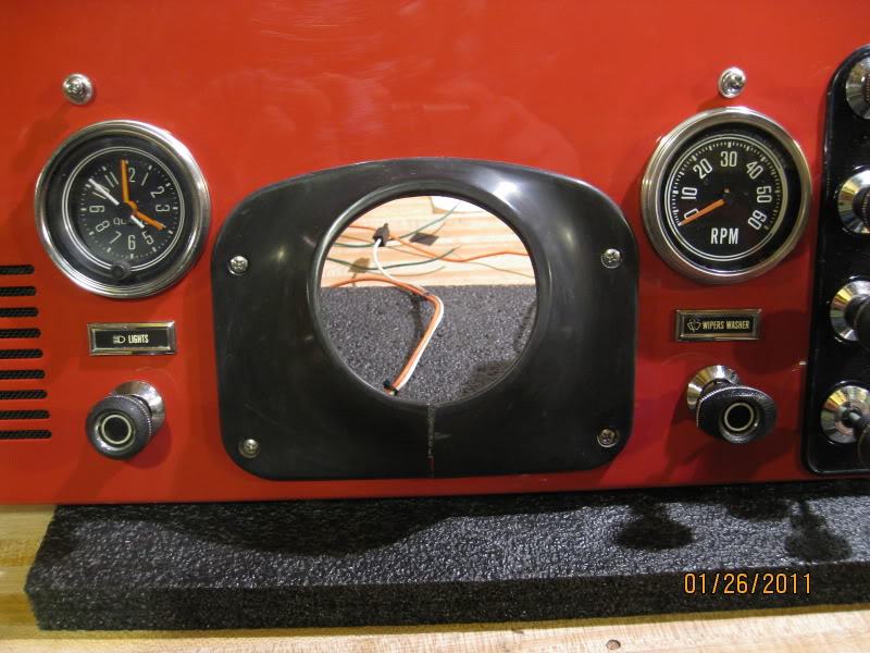
This picture is from Keith's dash
restoration project. The entire restoration of his hash
can be seen at this link.
http://www.jeepforum.com/forum/f8/cj-dash-restoration-classic-look-1150715/index16.html#post13371355
|
|
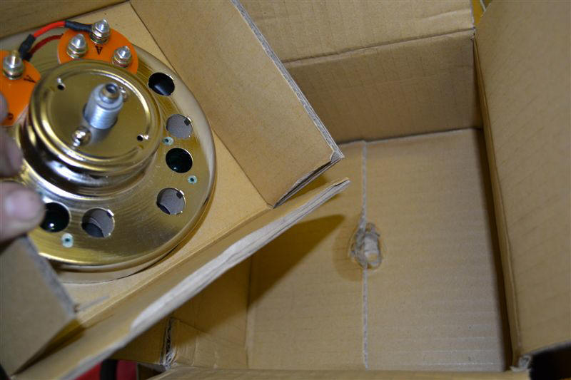
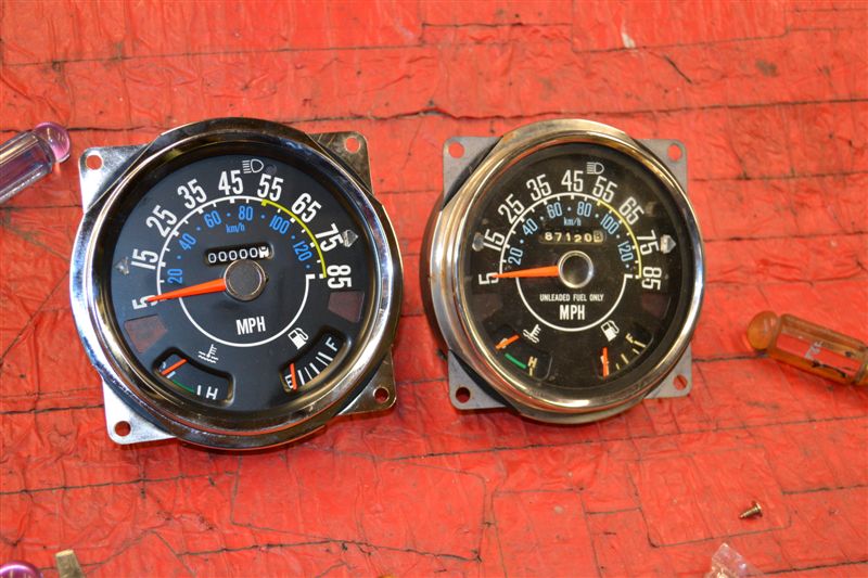
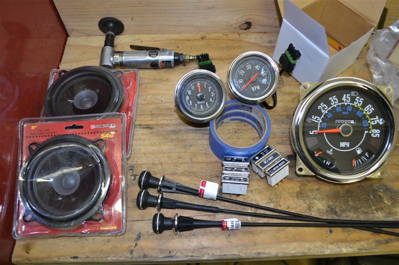
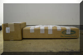
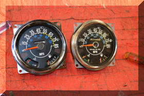
Next up Replace the Speedometer
You have got
to be kidding me.
The
aftermarket on Jeep parts really sucks!
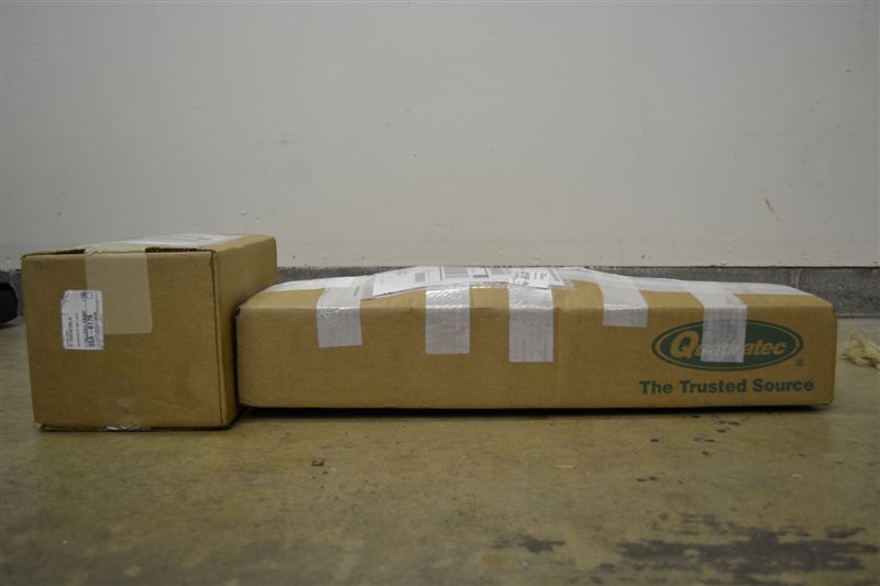
I ordered a
new speedometer for the jeep. The first one that came
from quadratec was packed so bad that the speedometer
was damaged in transit.
Called them
up and they promised to have one here by the weekend so
that I could install it. That did not happen.
|
 |
 |
 |
 |
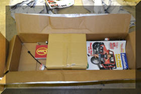
| Went to
install the replacement and the back does not have a
hole for the bottom dash light, and there is an extra
hole in the upper right as you face the back of the
speedometer that lights nothing (I put a flash light to
it and it is not an indicator or instrument light). I think what
I am faced with is removing the back to the old gauge
and the new gauge, swapping the guts of the new gauge to
the old housing so that I can keep the bottom stock dash
light. |
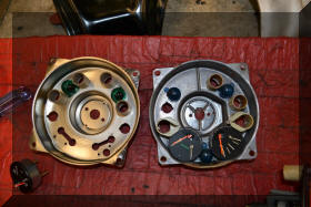 |
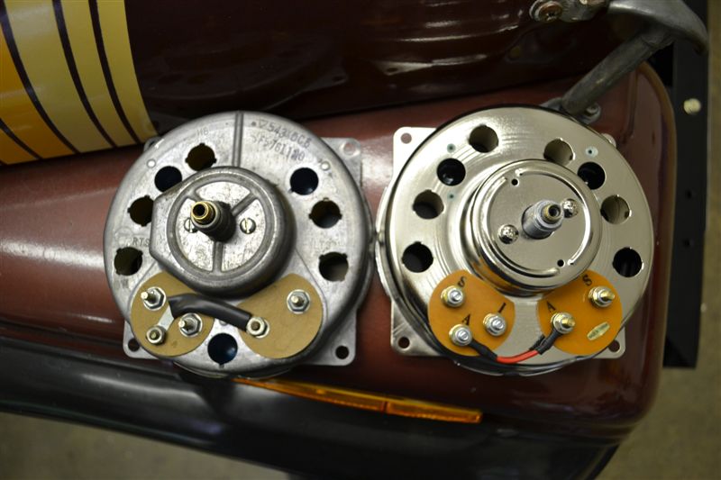
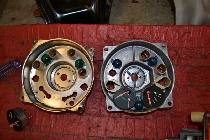
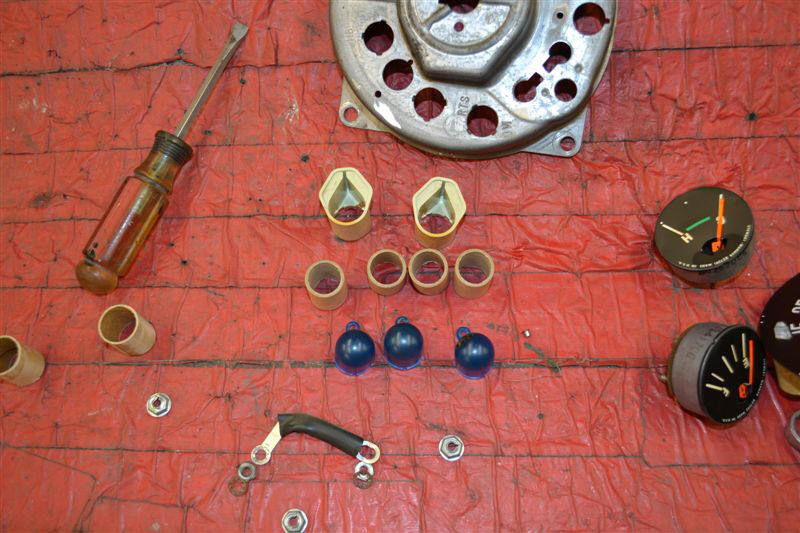
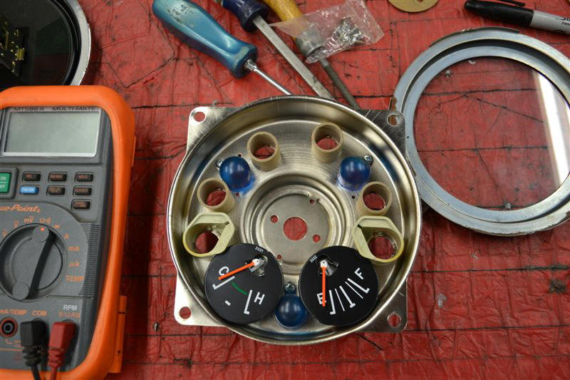
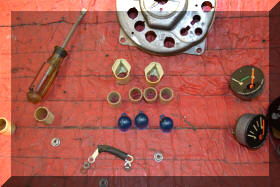
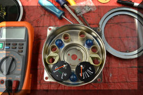
Opened up the speedometer and
found that the light gels were not the same color, the
tubes for containing the brake and 4 wheel drive lights
were missing. The holes that holed the speedometer are
not in the correct position. I decided to drill the
missing hole in the aftermarket housing and transfer the
gels and tubes from the old to the new |
 |
 |
 |
Transfer complete, lets just hope
that the new gauges work! |
|
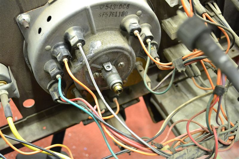
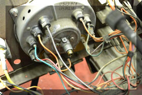
I took lots of pictures of the back
side of the dash so that I could figure out where all the
wires were attached and then removed the old speedometer
and installed the new one. Now all the gauges and
indicator lights work except the fuel gauge. I believe I
will have to replace the sending unit in the tank |
 |
 |
|
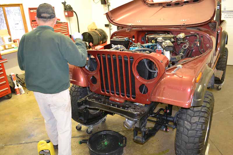
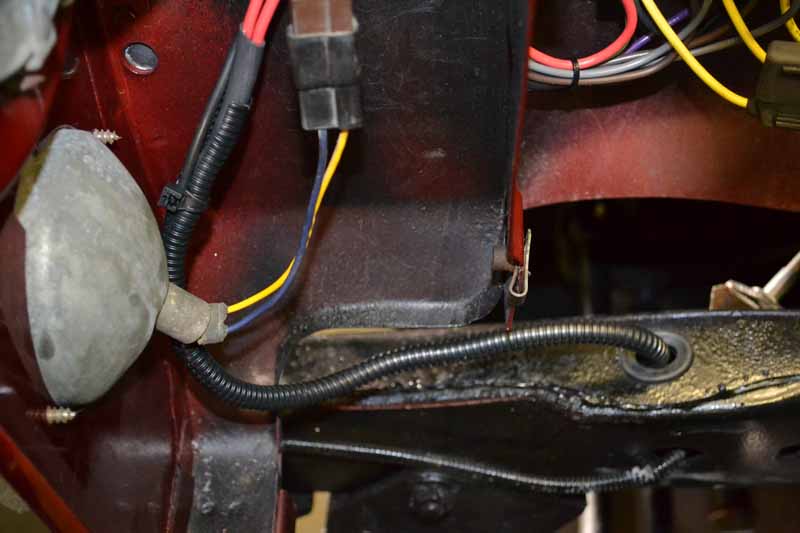
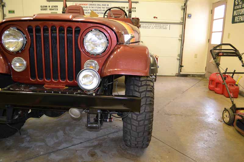
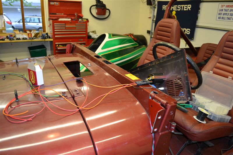
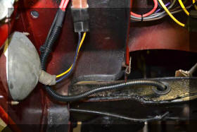
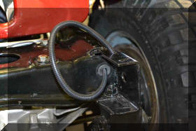
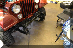
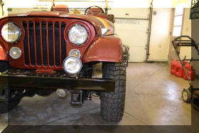
Started working on putting the front bumper back on. I
want to put driving lights on the front of the Jeep and
the Original Owner had some retro KC lights that were in
good shape. So... set up a relay to power them
(triggered by a switch on the dash and high beam head
lights). Ran the wires through existing holes in the
frame in the engine compartment (using gruments) and
drilled some new holes outside. |
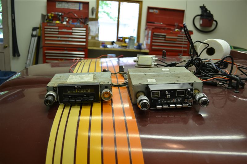
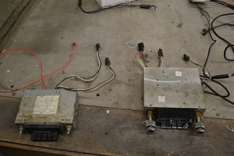
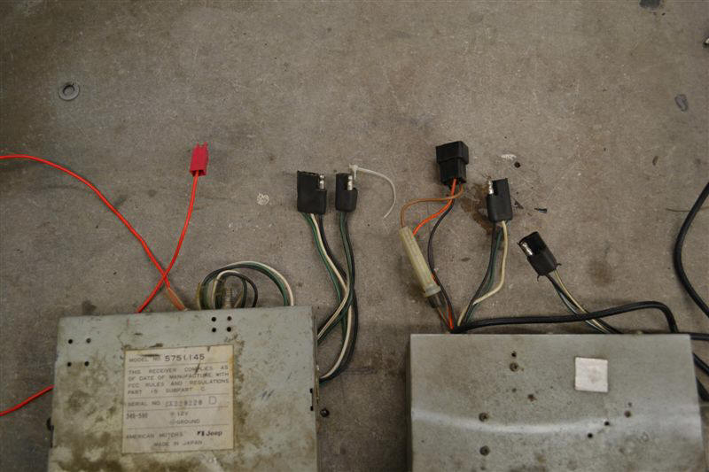
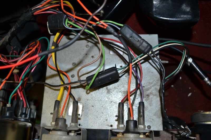
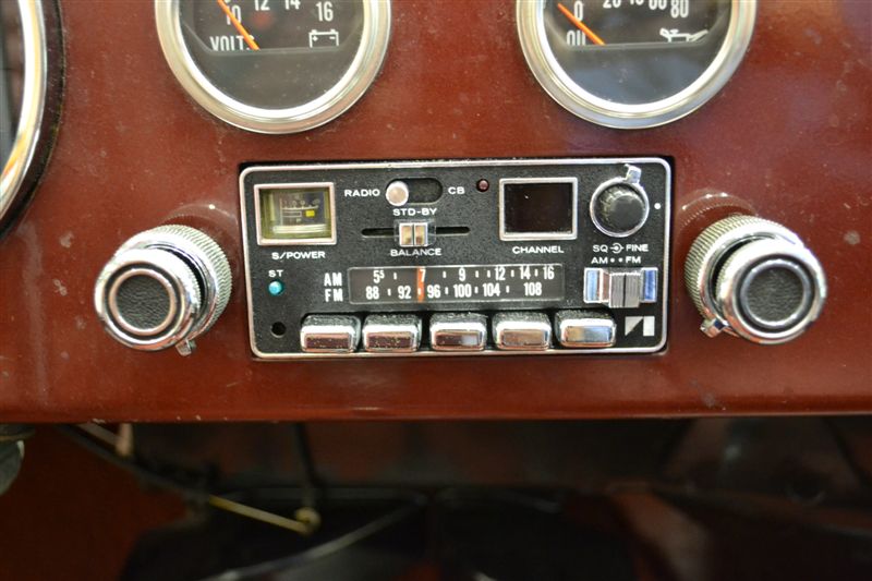
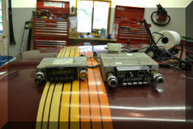
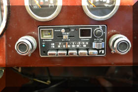
| Replace the AM/FM radio as the left channel does not
work and the tuning knob is broken off
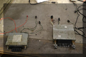
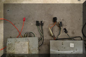
The radio I'm using to replace the
original radio is an original AM / FM Stereo / CB Jeep
radio I go off of Fee Bay. The wiring looks much more
complicated that it actually is. I did get the splitter
transformer that allows me to use the stock FM radio
antenna for the CB antenna. The speakers plugged right
up to the speaker wiring under the dash. The old radio
only had a power feed, this one has a dash light feed
and a power feed. The orange wire is for the dash
lights, brown is power |
 |
 |
 |
 |
 |
|
 |
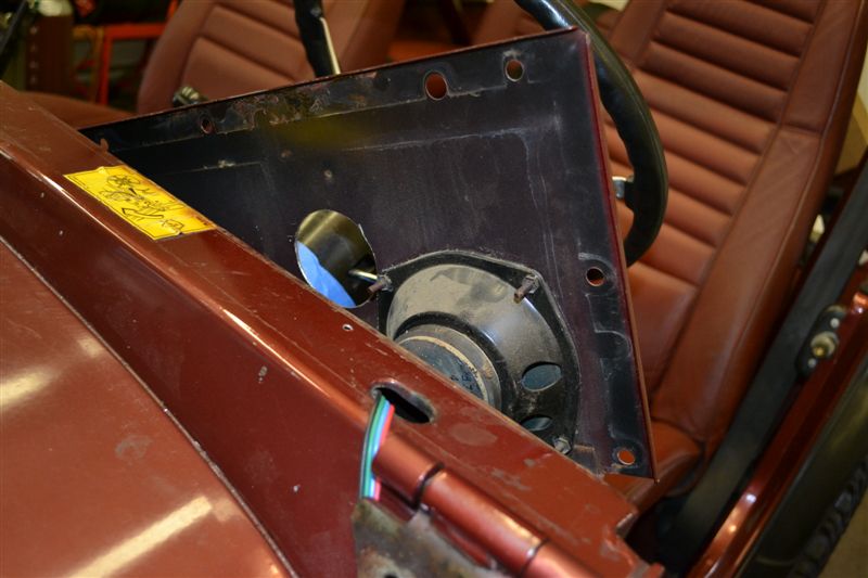
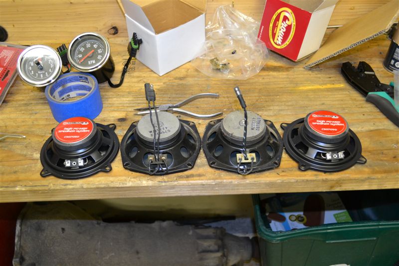
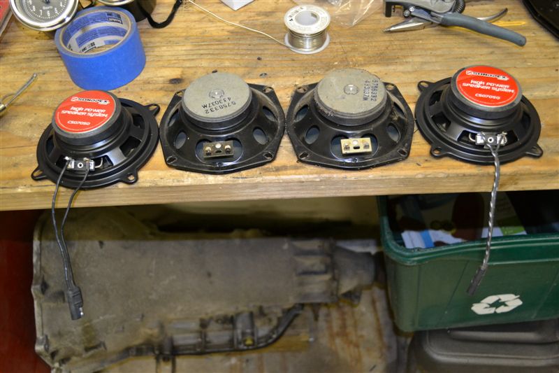
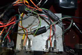
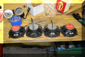
I removed the old speakers and
installed new speakers purchased from Pep Boys. They are
just cheat speakers as I have no intentions of putting
an expensive system into the Jeep. If you are going to
do this be careful as the space behind the drivers side
speaker is limited because of the emergency brake pedal
bracket. The speaker cones are plastic so a little rain
will not hurt them. I intend to run topless as much as
possible |
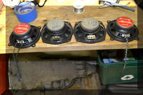
| I
removed the connectors of the backs of the old speakers
and installed them on the new speakers so they just
plugged up to the old wiring harness |
 |
 |
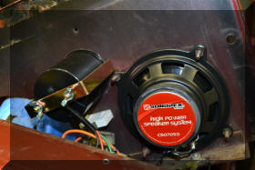 |
New speaker is now installed. take
note of how close the speaker mount is to the new clock.
If you are drilling the hole for the clock make sure you
take this into account. |
|
 |
Replace all the heater control cables. |
| So on
the surface form the first two pictures thus did not
look like much of a task, but I hope you now realize
that it was a lot of work |