| I have
started to complete an number of small tasks that need
to be completed before the Jeep can be driven down the
road, First up is installing longer flexible brake lines
needed because of the lift. This left to be done is the
rear one. That looks to be changeling as the lines are
rusted up. I may have to replace some of the steel line. |
 |
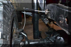 |
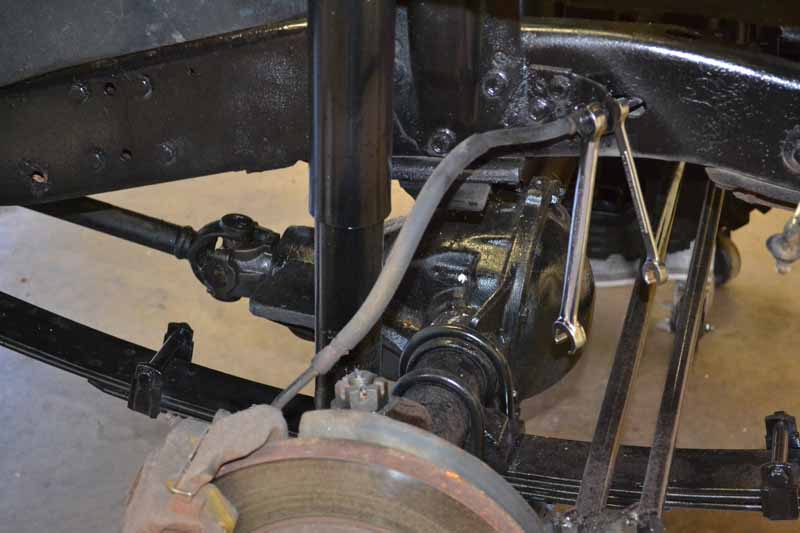
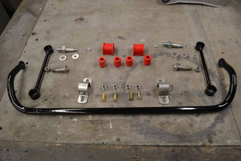
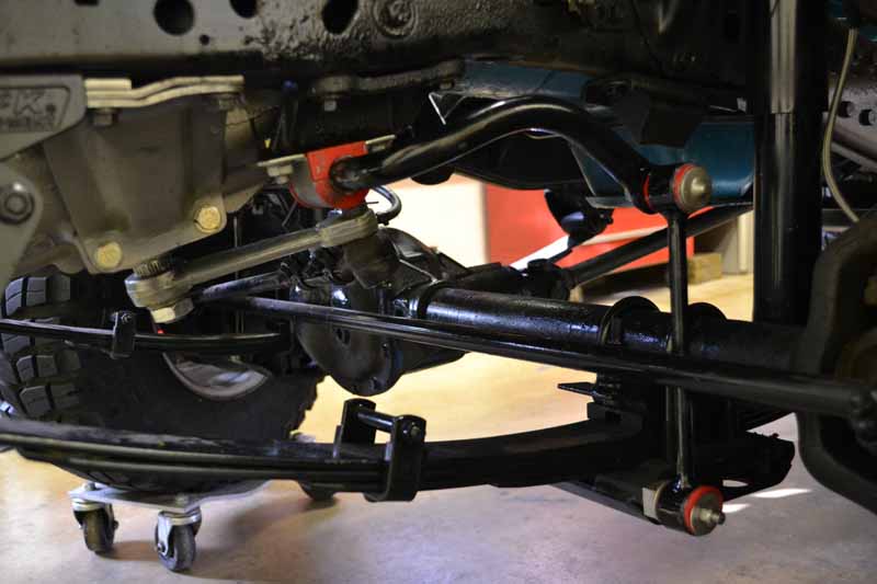
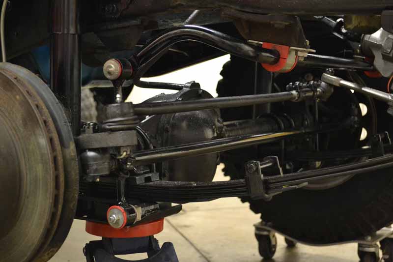
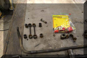
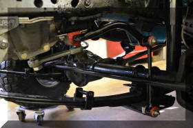
| Next
up is putting the sway bar back in. The links needed to
be lengthened also because of the lift. |
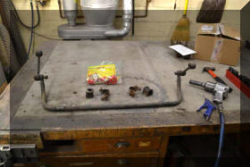 |
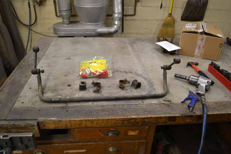
The previous owner had purchased
polyurethane bushings for the sway bar. I am not a fan
of polyurethane, and the red is a little much but they
came with the jeep and they are "free" so I will install
them |
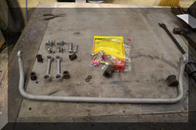 |
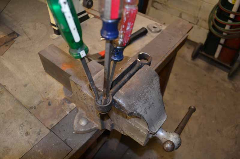
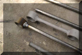
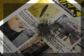
A little sand blasting to clean
everything up. |
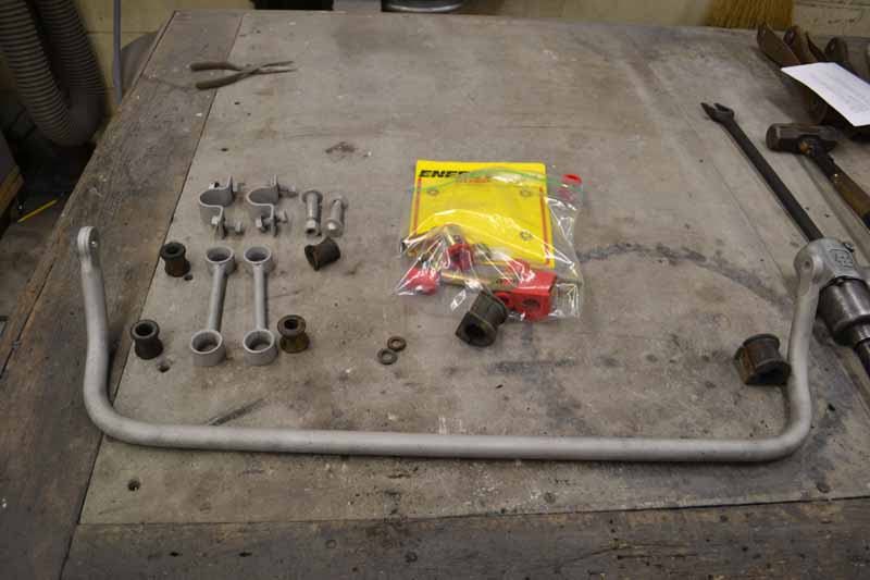
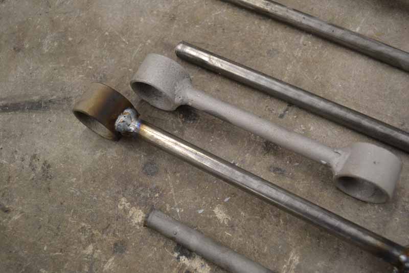
| A
little cutting and welding and the sway bar links are
now 3 1/2 inches longer. I used that measurement because
that is how much I need to drop the pitman arm to get
the tie rods parallel. |
 |
 |
 |
 |
 |
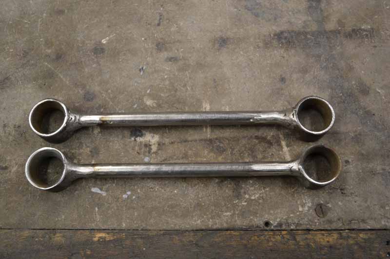
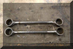
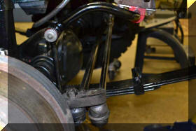
Through the magic of powder coat
they look like new |
 |
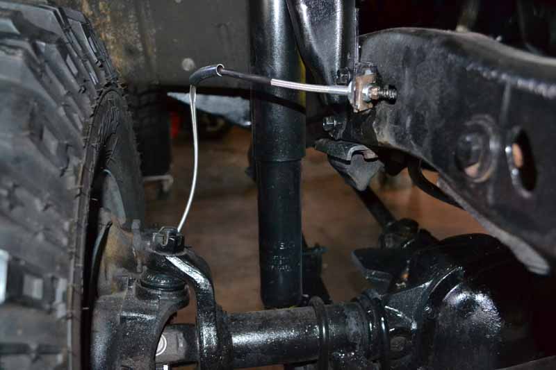
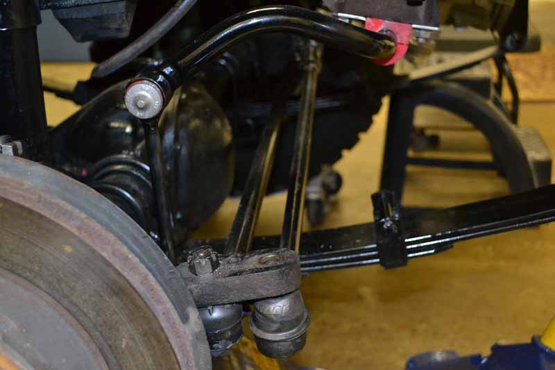
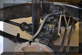
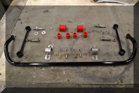
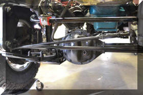
Looks pretty good on the Jeep. You
can see the pitman arm in this shot, the new drop pitman
arm should arrive tomorrow. |
 |
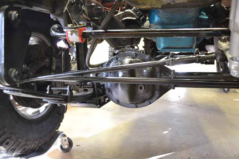
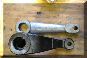
So I want to get the drag link and tie rod even to get
rid of bump steer. One of the problems with the drop
pitman arms available is they are shorter than the stock
pitman arm and there for the turning radius is not as
good. The second problem is shortest drop pitman arm I
can find is 3 inches and that puts the tie rod about 1/2
inch below the drag link. If any thing I would want it
above the drag link for ground clearance. |
 |
 |
 |
What to do? Well this question cam up on the JeepForum
and a tie rod swap was suggested. After putting the the
stock pitman arm back on and popping the other end of
the drag link off and setting it in place on top of the
spindle, it appeared that that would almost put the tie
rod and drag link parallel to each other. There are
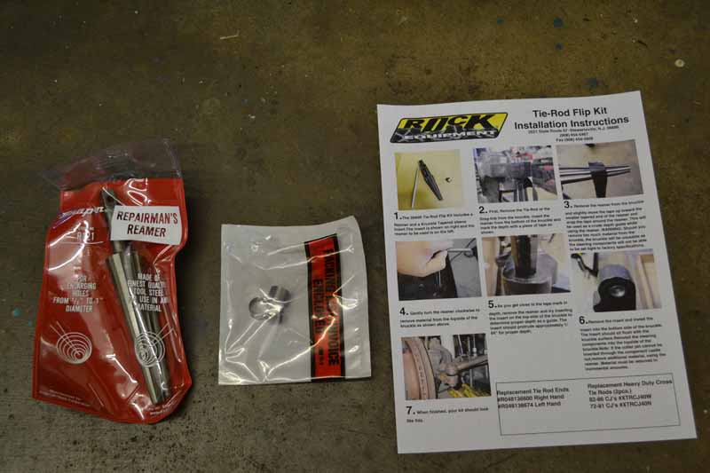
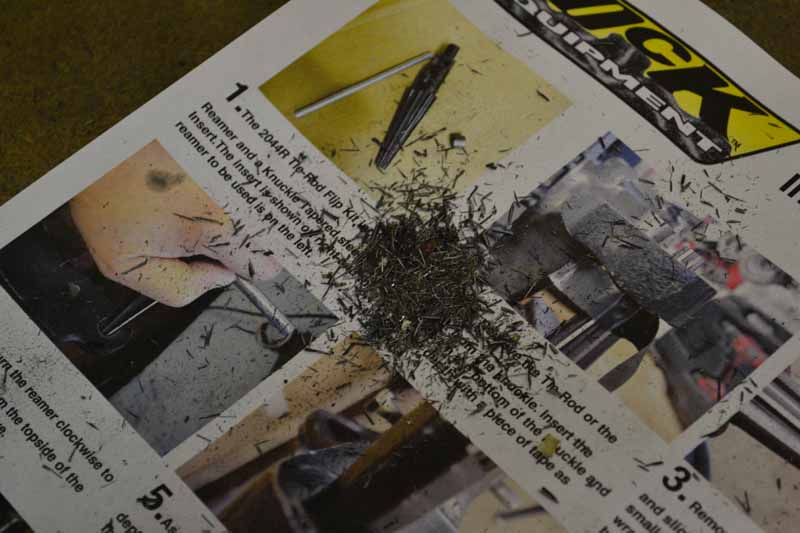
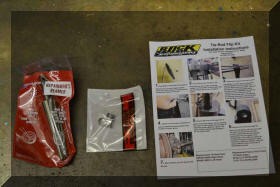
several kits out there to do this but I purchased Rock
Equipment's Tie-Rod Flip Kit which included the Reamer
(a Snap-On tool, the good stuff) |
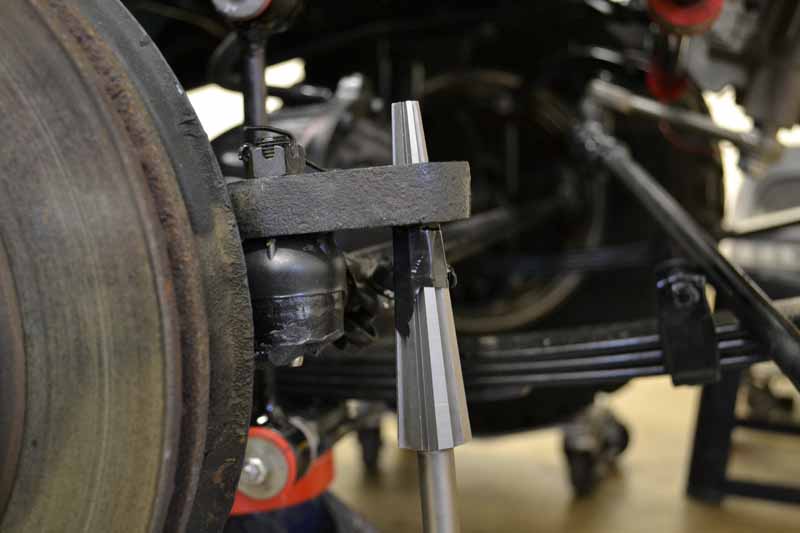
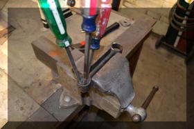
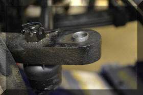
| This
will be kind of a repeat of the instructions included
with the kit. The first step is to remove the drag link
and insert the reamer from the bottom of the knuckle.
Mark the depth that the reamer enters the hole with some
tape, remove the reamer and move the tape up slightly up
towards the small end of the reamer. If you remove to
much material the spindle is unusable. By taking this
percaution you insure you will not remove to much
material |
 |
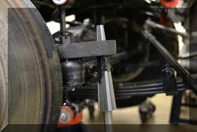 |
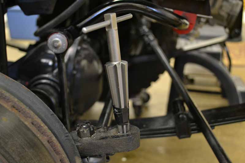
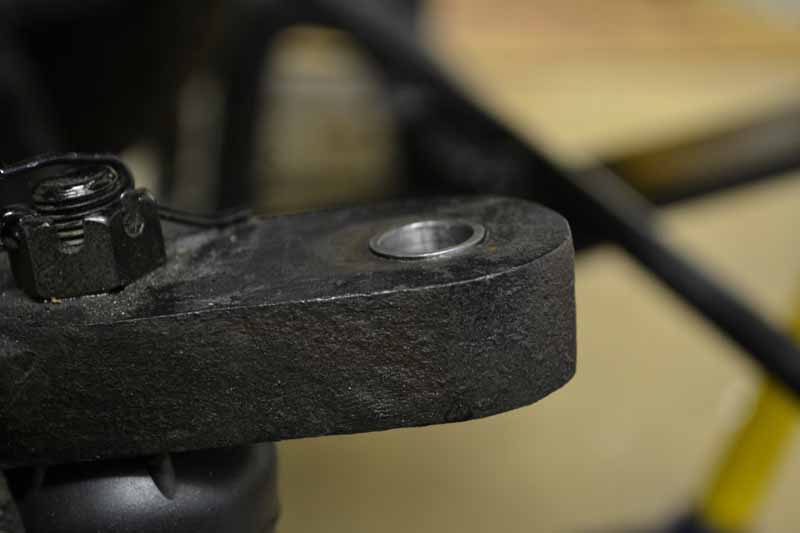
| Now
you insert the reamer from the top side and gently turn
the reamer clockwise to remove the material from the top
side. As you get close to the tape mark in depth remove
the reamer and try inserting the insert on the top side.
The insert should protrude approximately 1/64 inch for
proper depth. Remove the insert and install the insert
into the bottom side of the knuckle. the insert should
sit flush with the knuckle surface. To get mine to be
flush the insert had to be slightly below the surface
from the top side. These knuckles are a case piece so
this will be different for everyone. I am glad that this
is a hand tool as the amount of material that you remove
is not all that much. Also as the reamer goes in it is
not completely smooth so I was able to concentrate on
the high spots in the cone as the reamer went in and
ended up with a completely round smooth cone. |
 |
 |
 |
 |
 |
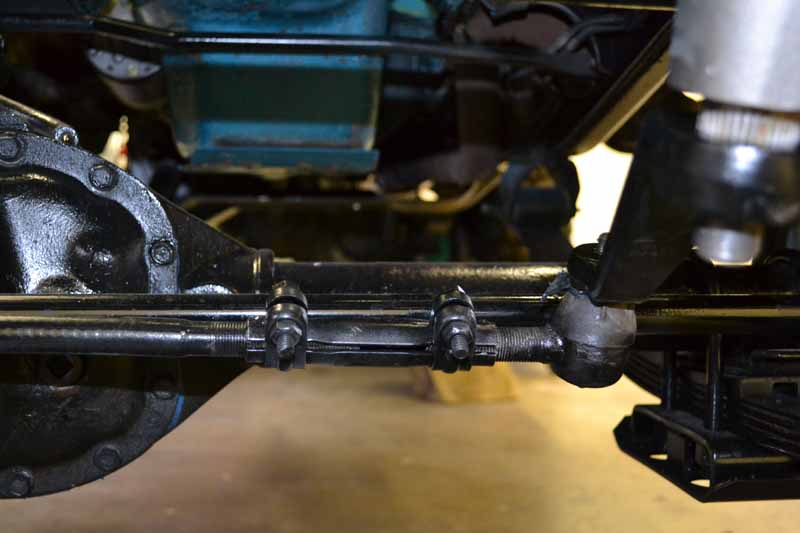
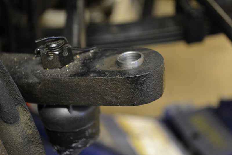
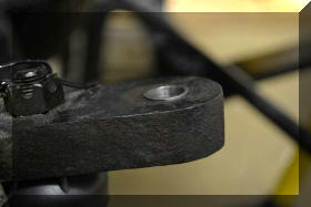
So now I have the insert almost
even with the bottom of the knuckle. It takes very
little material to make a difference at this point, go
slow. |
 |
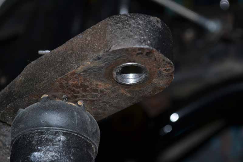
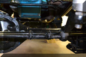
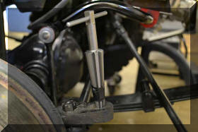
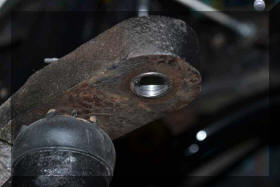
Here is the tie rod installed. The
drag link is just slightly higher at the pitman arm, but
that is perfect as the springs will settle.
I am not at this point gooing to flip the tie rod as I
have been reading of problems with clearances between
the tie rod and pitman arm when flipping both the tie
rod and pitman arm. I'm very happy with the kit at this
point. |
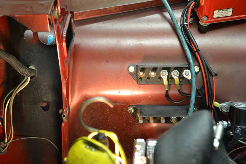
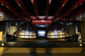
| Now
here is a task I have been putting off, but have now
finally gotten around to. We have all heard the stories
about the dim head lights on these CJ's caused by the
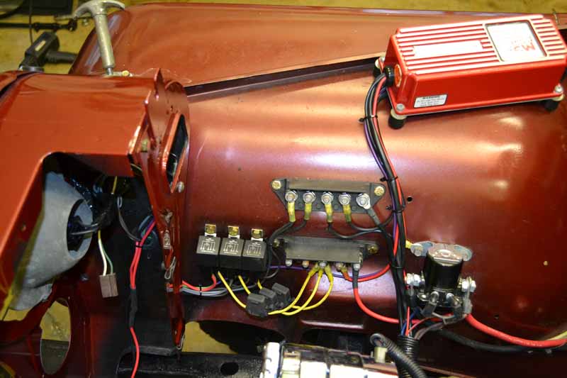
lite gauge wiring used and the poor grounds. I install
three relays, one for the low beams, one for the high
beams and one for future driving lights. The relays are
all 40 amp rated, all the wiring is in 12 gauge wire,
fused at 30 amps. The ground and the power are direct
feeds from the battery. What a difference in the
brightness of the head lights, and these are not even
halogen! The driving
lights will have a switch somewhere on the dash board.
The trigger for the driving lights will only work whe
the high beams are on, by that I mean if the high beams
are on and the switch is on the driving lights will come
on. If you dim the head lights to low beam it will
automatically turn the driving lights off. These will be
driving lights not fog lights.
|
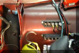 |
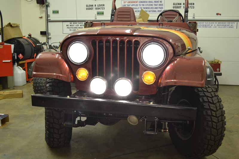
This is before the relays have
been added |
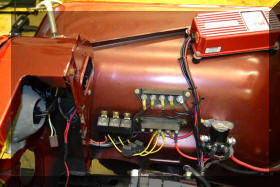 |
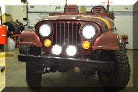
This is after |
 |
 |
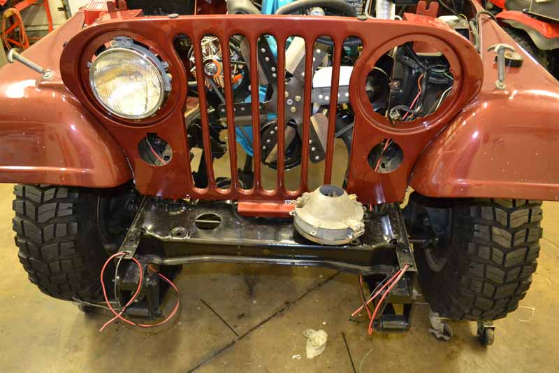
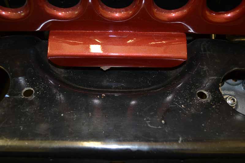
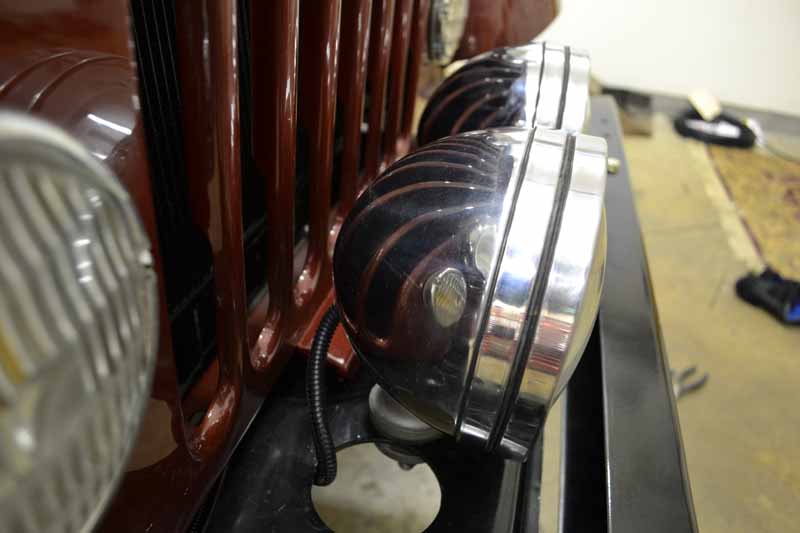
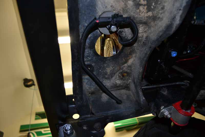
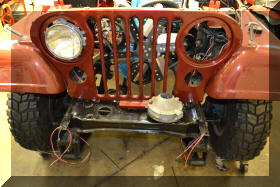
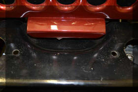
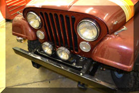
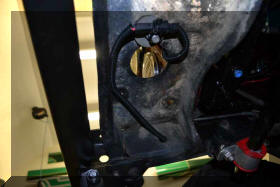
| Note
that the wires for the driving lights are at the bumper
mounts and that there is both a hot and ground. When I
picked the Jeep up one of the chrome rims around the
head ligh was not mounted and now they both are mounted.
Progress! I now need to complete the wiring on the dash
for the driving lights.
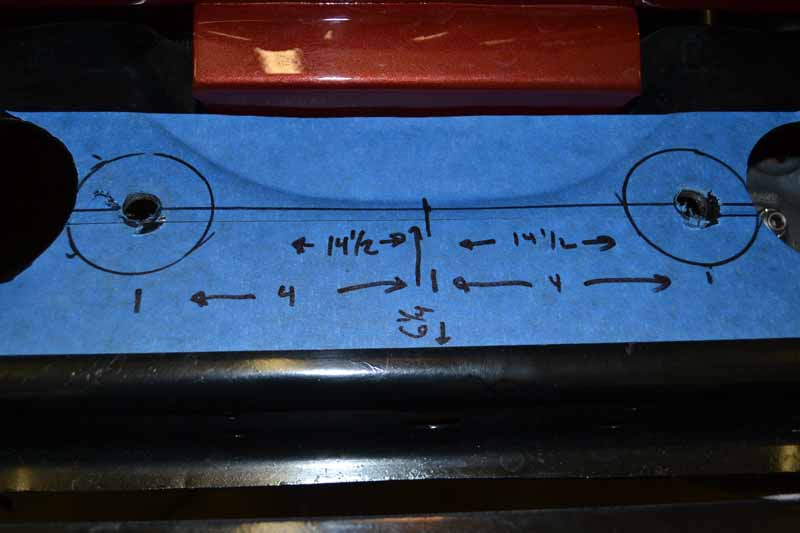
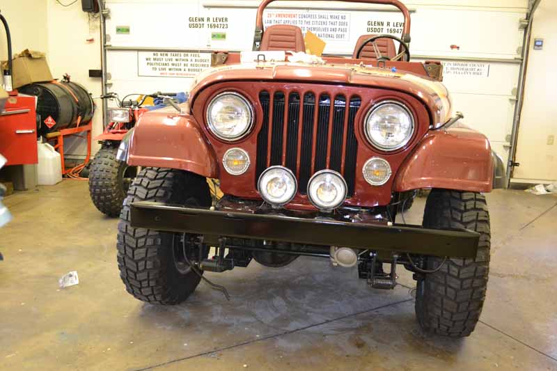
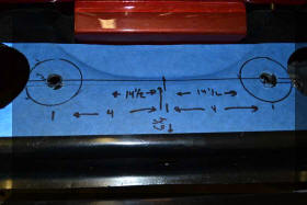
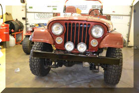
Well I got to mount the driving lights today. There were
three logical positions to mount them as there were
already holes to mount them in from the factory. True to
form I elected to pick a fourth position and drill new
holes. This position is clear of the turn signals and
away from the tires so that mud will not get slug on
them, (the forward measurement is from the front of the
bumper, and the side measurement is from the outside of
the frame rail). |
 |
 |
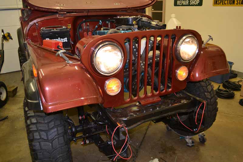
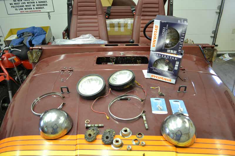
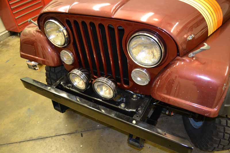
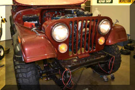
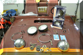
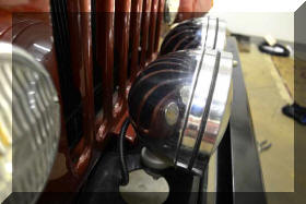
| Now
that the holes are drilled it is time to clean up these
20 ? year old parts, and replace the original headlights
(I know some restorer out there is going to hate me but
I throw out the old headlights) with some halogen
headlights. I buffed out the headlight rings, and the
driving light buckets on a buffing wheel. They came out
really nice. I painted up all the hardware with
Eastwoods detail gray. |
 |
 |
|
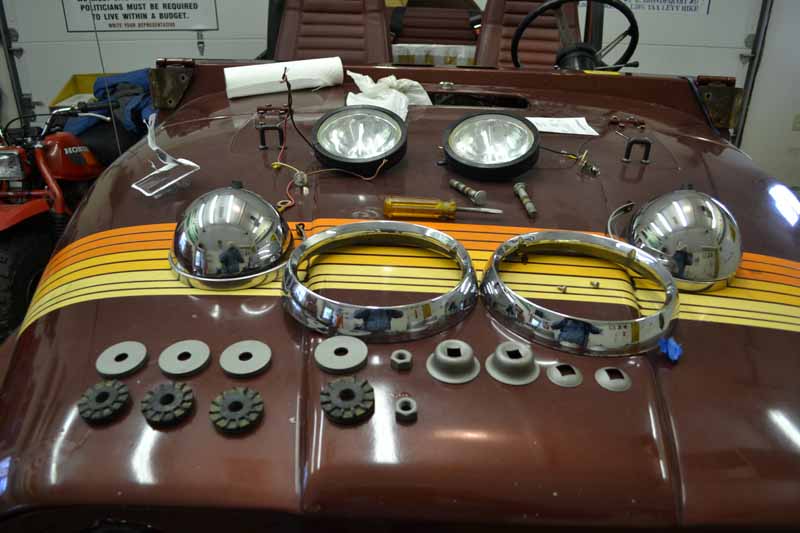
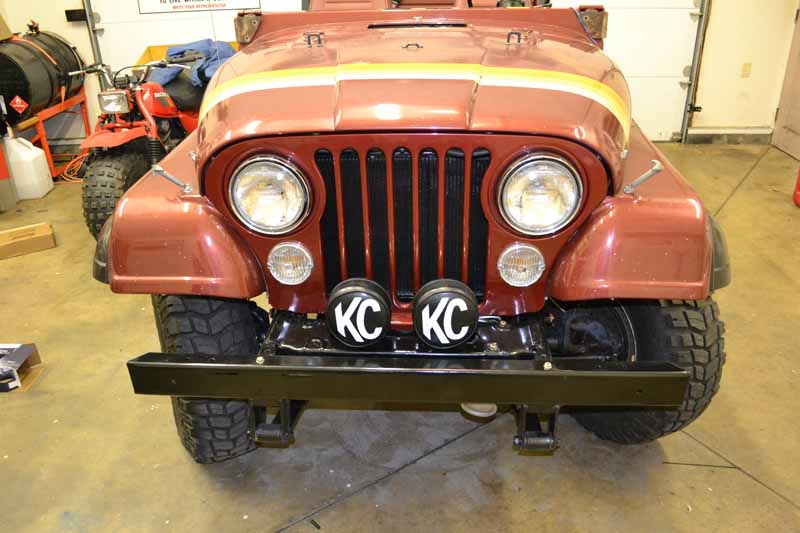
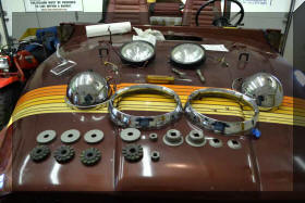
So..... this is what they look like mounted up |
 |
 |
 |
 |
 |
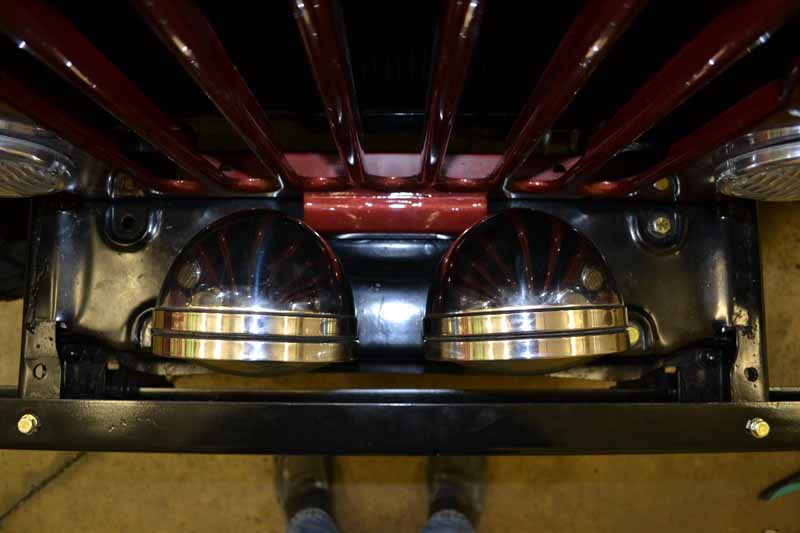
I used weather pack connectors and
all the wirering is now routed through existing holes in
the frame |
 |
The 12 gauge wires and dedicated
grounds were worth the trouble! |
 |
|