|
REMEMBER TO CLICK PICTURES FOR MORE DETAIL /
LARGER PICTURE
|
|
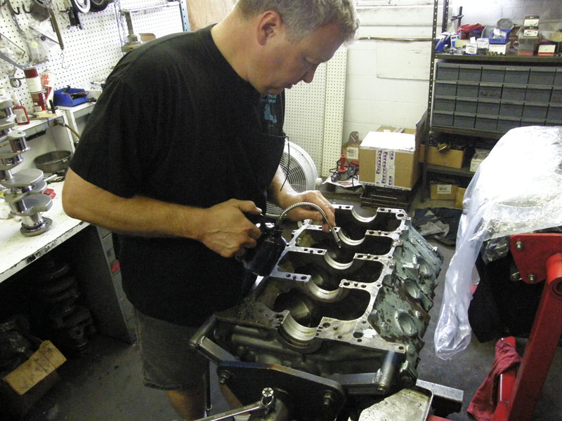
Ok, so we are still building the engine. The
theme this week is aftermarket parts do not fit. How do they stay in
business, I guess because no one makes stuff that fits, because if
they did they would put everyone else out of business. Read on and
see what you think. |
|
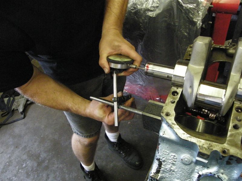
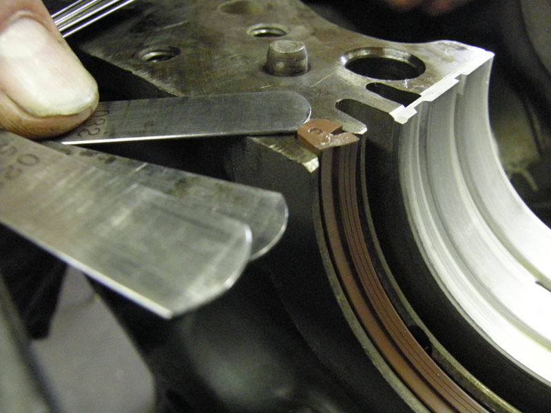
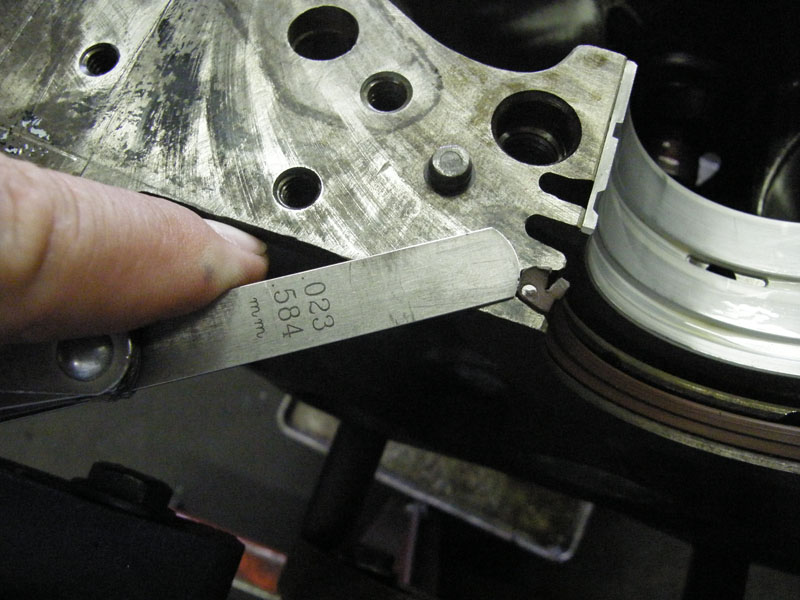
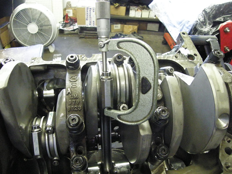
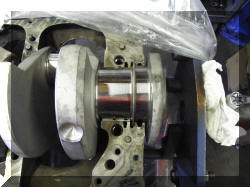
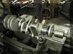
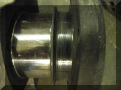
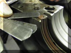
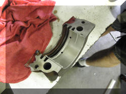
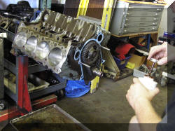
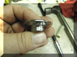
The first problem this week with aftermarket
parts was with the new crank shaft. The oil separator ring on the
crankshaft was actually hitting the block. It had to be put into a
lathe and turned down to allow the correct Crankshaft end play without hitting the block. This was checked by putting blue indicator on
the ring, putting it in the block, putting pressure on the
crankshaft and rotating it. |
 |
 |
 |
 |
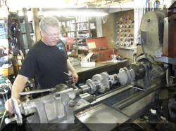 |
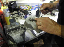
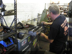
Here is the master at the lathe |
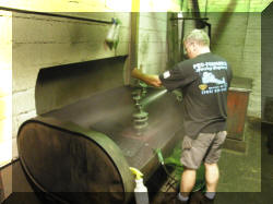 |
Getting rid of the shavings |
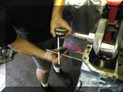 |
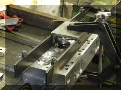
Checking Crankshaft end clearance. |
|
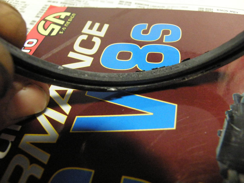
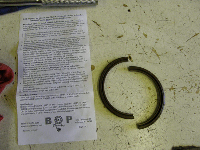
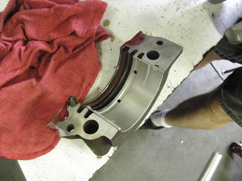
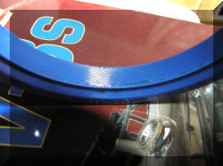
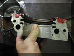
The second topic of discussion is the rear
main seal. The factory-style rope seal worked fine when installed at
the factory. Unfortunately replacement rope seals were redesigned
several years ago, and the material that worked best, asbestos, was
replaced with fiberglass. . In
addition on older crankshafts the area the seal ran on was
serrated to throw oil back into the oil pan, and the seals were
smooth. |
 |
 |
|
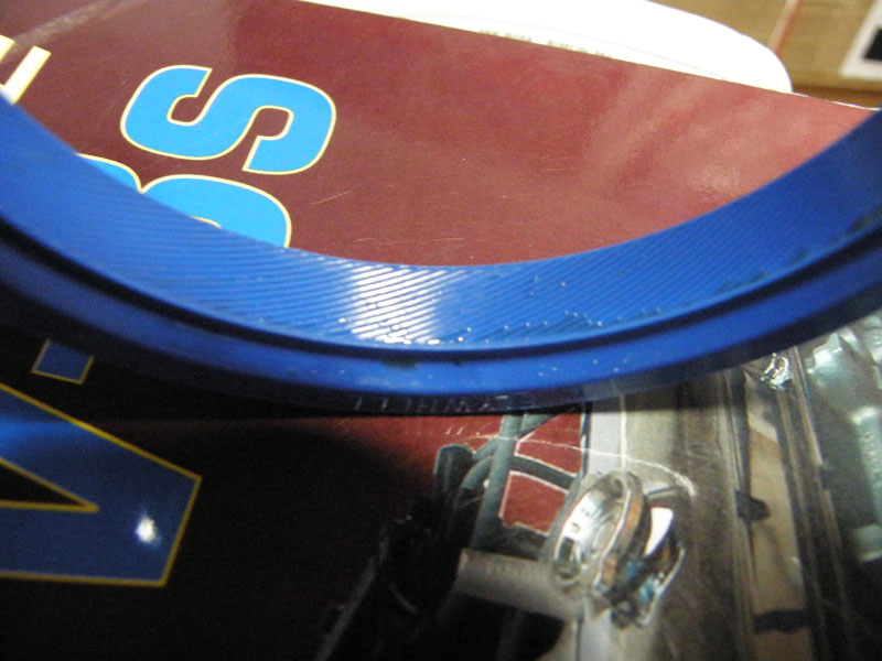
A newer design was a smooth crankshaft surface
with the serrations in the seal |
|
|
 |
|
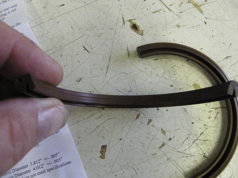
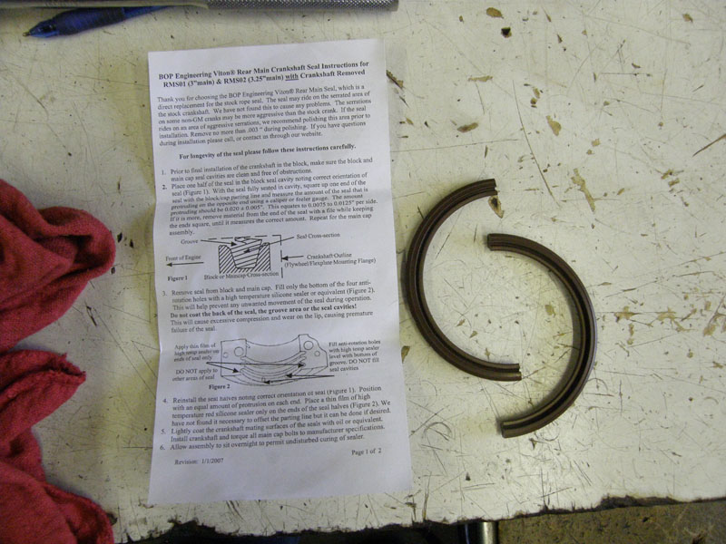
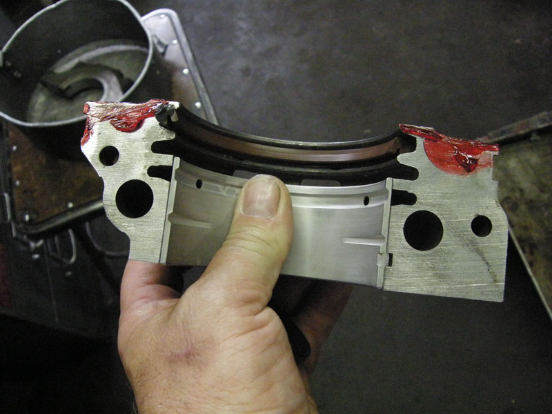
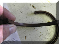
A third design is a smooth crankshaft with a
lip on the seal to hold the oil in. The seal that came in the gasket
set was the redesigned rope seal, the stroker crankshaft came with
the smooth surface on the seal contact point. I had to make a
change. Seals made by BOP Engineering are a two piece rigid section
that use Vitron sealing lips and require minor trimming to fit. Be
careful when trimming to assure the overall length is correct, the
mating surfaces are flat, and that the edges of the two pieces mate
with no gaps. |
|
|
 |
|
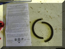
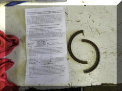
So, I ordered the BOP Engineering seal and had
it shipped overnight as we were stopped dead in or tracks. and this
is the install. |
 |
 |
 |
 |
 |
 |
 |
 |
|
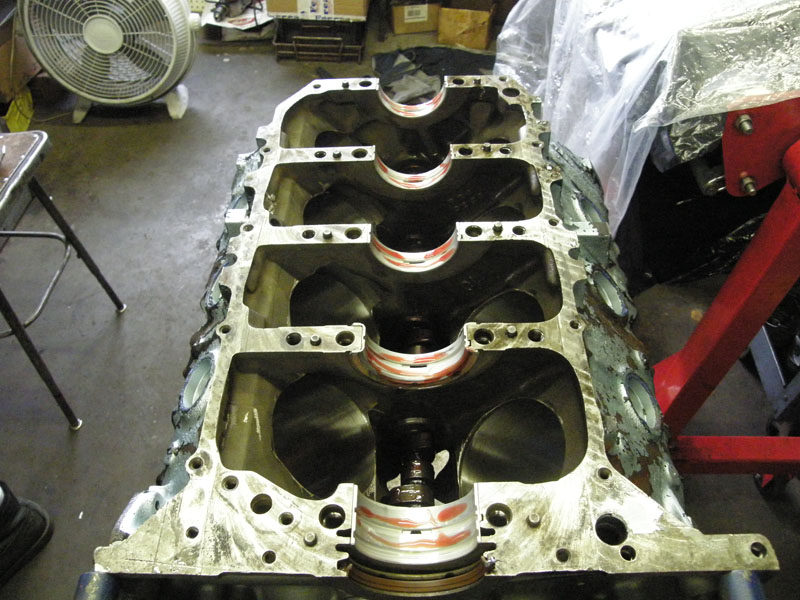
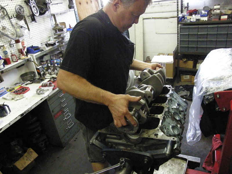
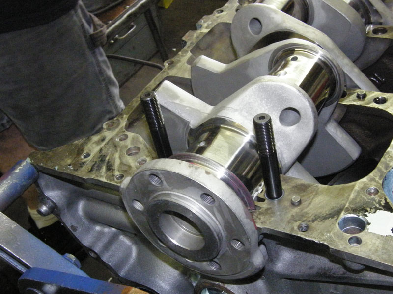
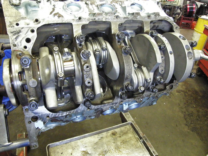
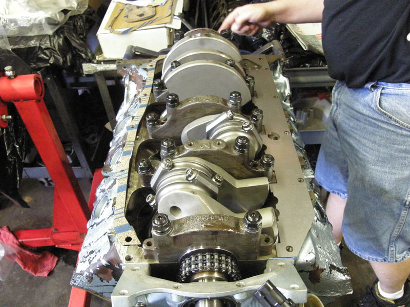
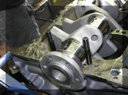
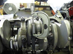
Ok, now we are finally ready to set the new
stroker steal forged crankshaft in. |
 |
 |
|
Install Main Bearing Studs, ARP of course. |
 |
 |
 |
Pretty. |
|
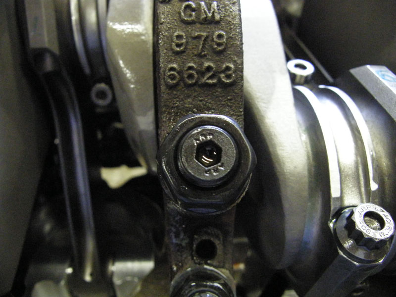
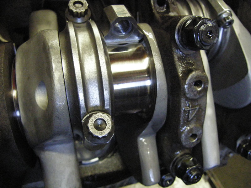
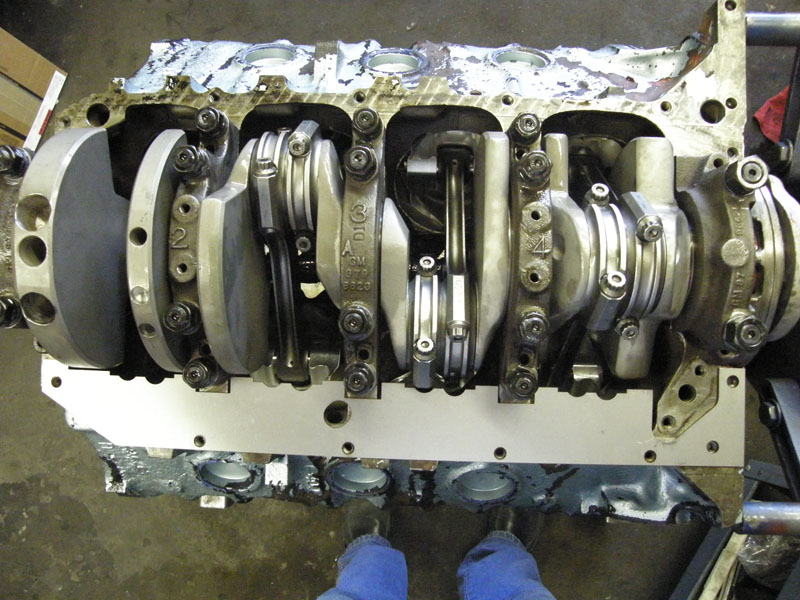
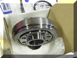
Time to install the new forged "H" beam rods.
To do this the Aftermarket rod bearings had to be sized to fit the
aftermarket crank shaft. |
 |
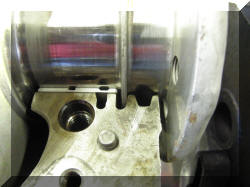
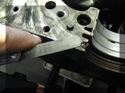
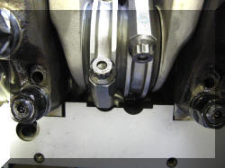
Here is what I mean. If you enlarge the
picture to the right (click on it) you will see that the rod bearing
has been chamfered so that it does not ride on the radius of the
crankshaft. If they had been installed out of the box the edge of
the rod bearing would have worn into the radius of the crankshaft.
Not the trust surface of the rods will ride against the trust
surface of the crankshaft. The trust surface of the crankshaft was
checked for smoothness. |
 |
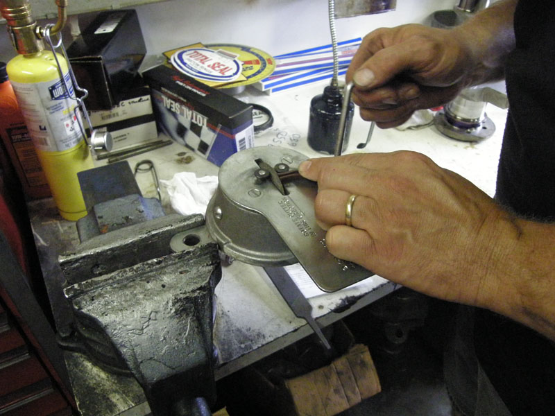
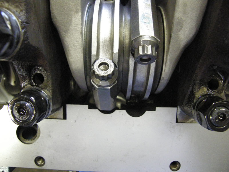
Once this was done the ARP rod bolts were
torqued to spec. |
 |
This was only used to get the bolts close to the correct tightness.
Bolt stretch was used to get the correct tightness. The way this is
done is the bolt is measured before an stress is put onto it. It is
then repeatedly measured until the correct stretch is achieved. |
 |
 |
 |
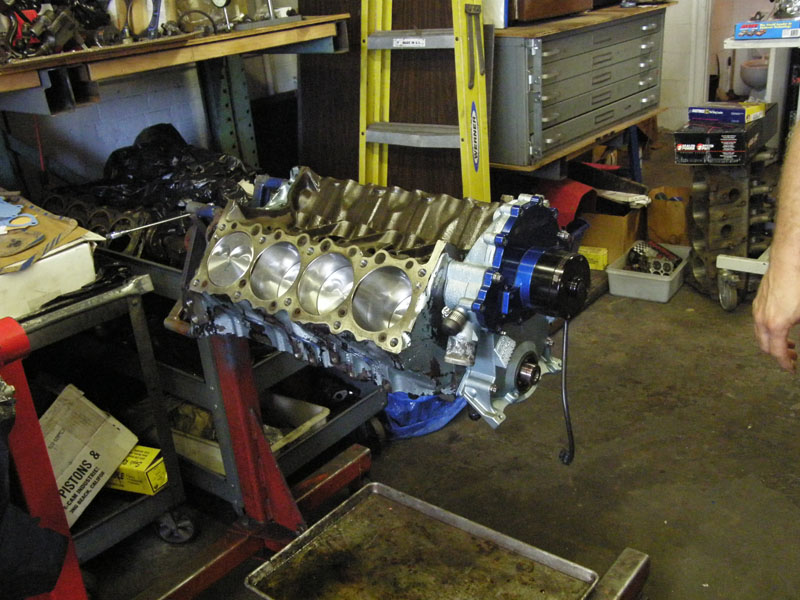
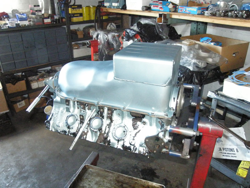
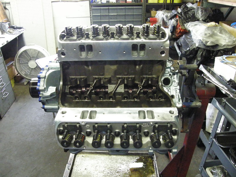
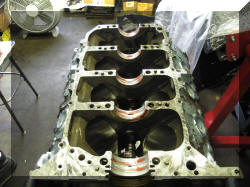
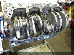
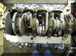
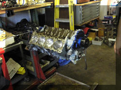
Rods, crank, and pistons are now installed. |
 |
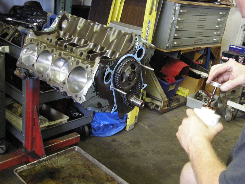
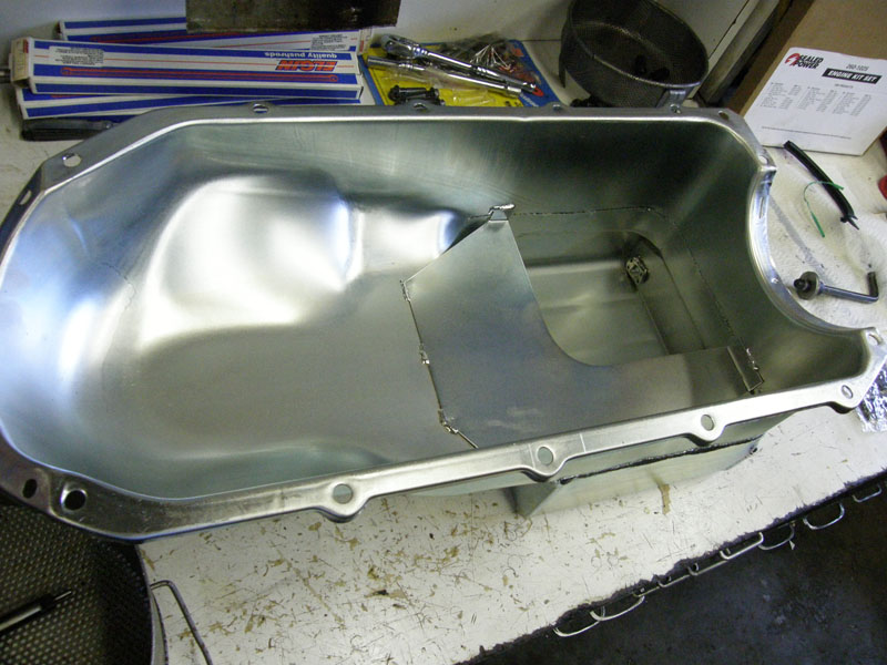
Put the oil pump in, weld the new pickup in,
check clearance to the bottom of the pan. New pickup is needed for
the new seven quart pan. |
|
Here we have an aftermarket part that fit. I
have replaced the windage tray with an oil scraper. |
 |
 |
|
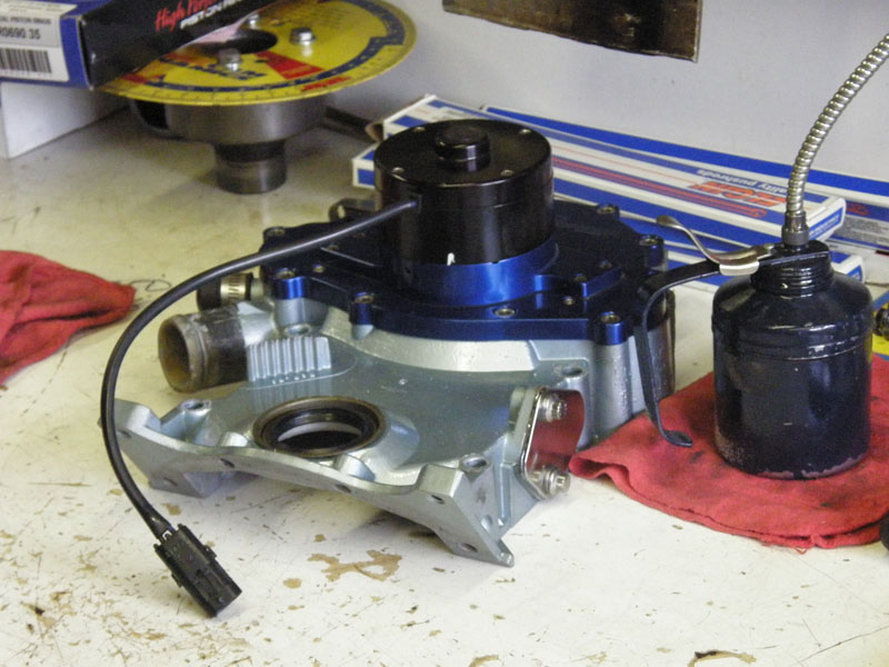
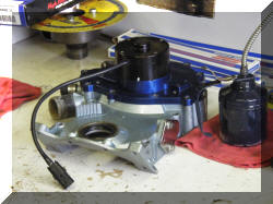
Next, install the water pump |
 |
 |
 |
 |
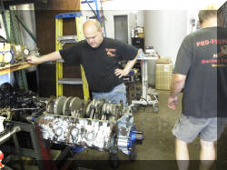 |
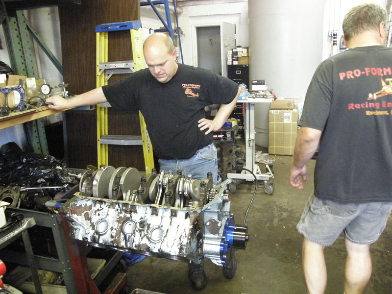
Is this engine ever going to leave this shop? |
|
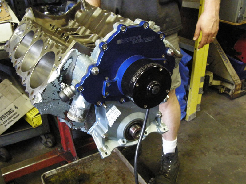
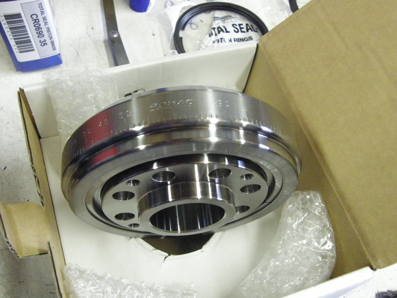
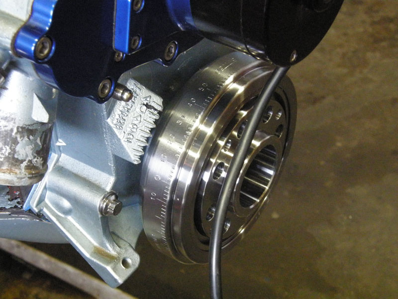
Now the brand new balancer. |
 |
 |
|
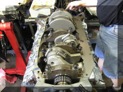
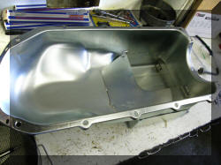
Time to button up the bottom, not forgetting
the dipstick tube. This is the fourth aftermarket part that did not
fit. The four holes in the front of the pan did not line up with the
bolt holes in the block. The holes in the pan had to be filed out of
round so that the bolts would fit. |
 |
 |
|
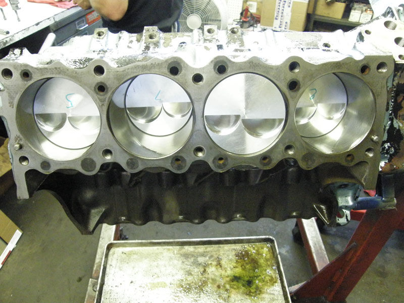
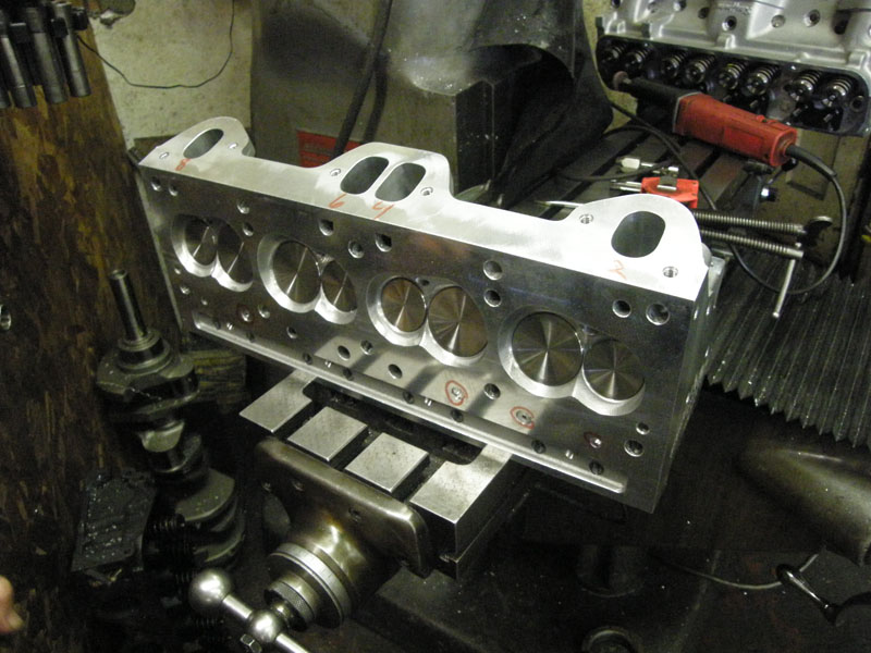
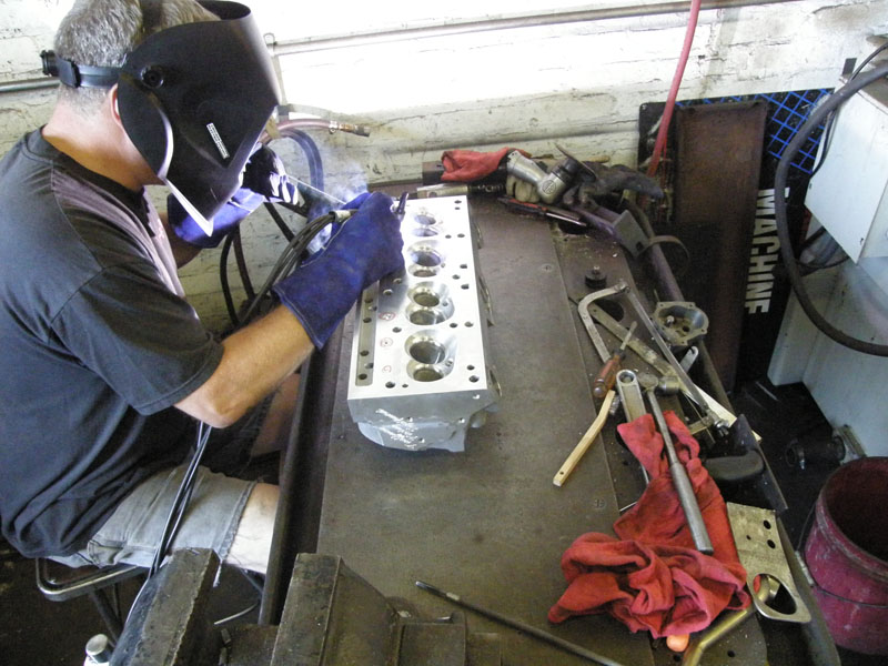
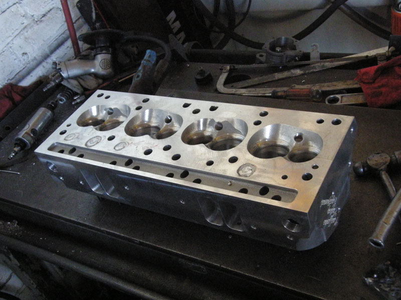
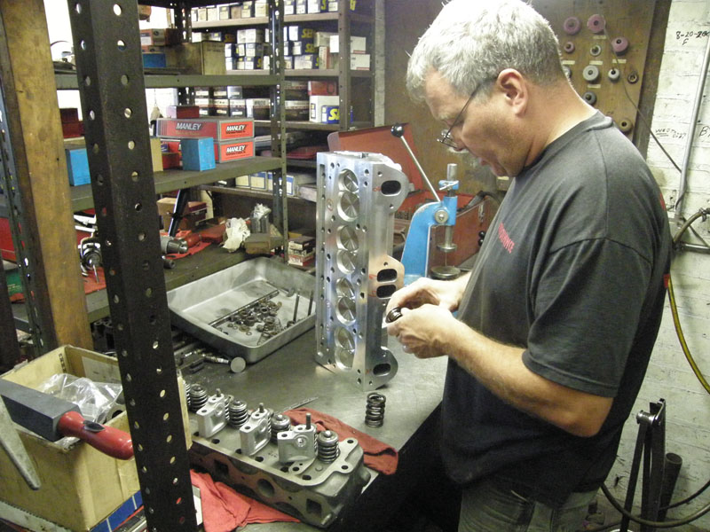
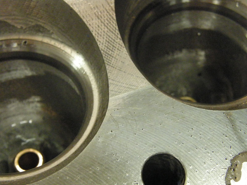
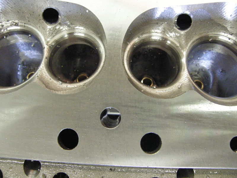
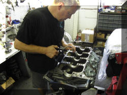
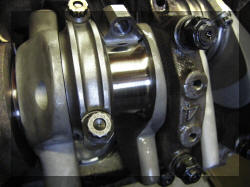
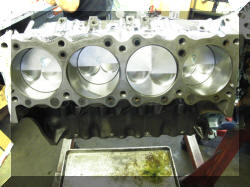
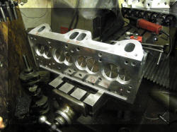
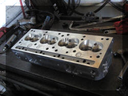
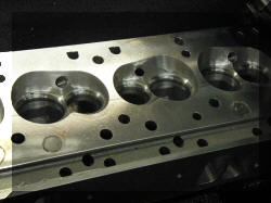
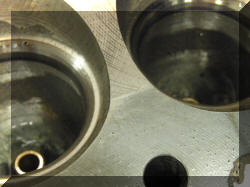
Now for the heads. They were very nice pieces
when we got them, but there was still work to be done. The first
task we did was on the last two engines the head gasket has failed
in the same spot. That spot was in a blind hole that went nowhere.
So aluminum plugs were inserted into these holes and welded up. That
is one of the nice things about aluminum. |
 |
 |
 |
 |
|
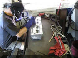
The next thing that was done to improve the
heads was to put Heil Coils into the head for the head bolts as a
precaution. |
 |
 |
 |
 |
 |
All done, these should last a long time now. |
 |
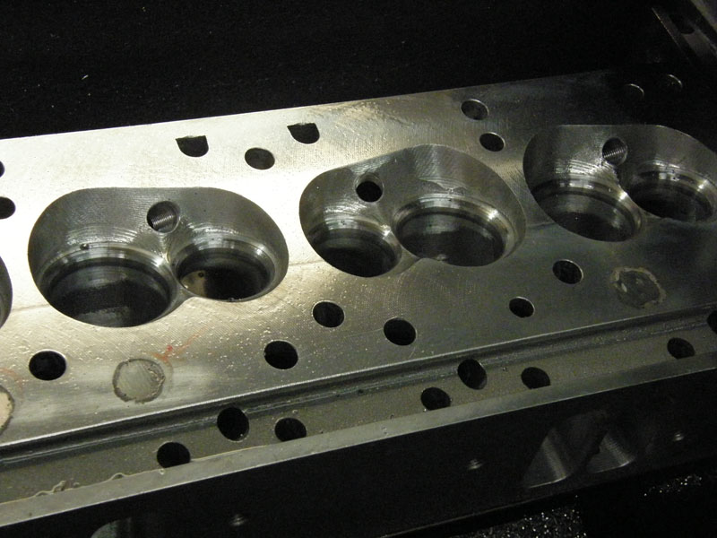
Next improvement was to smooth out the edges of
the oil returns |
|
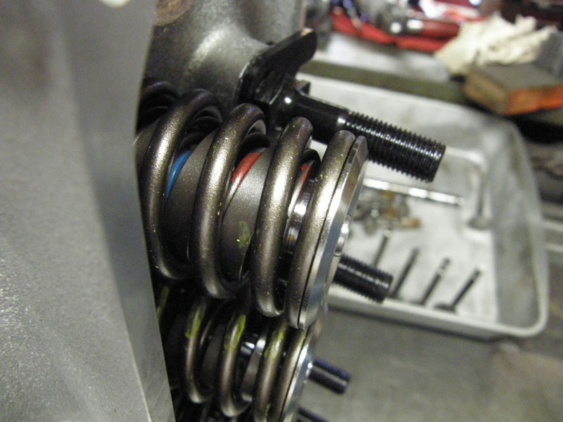
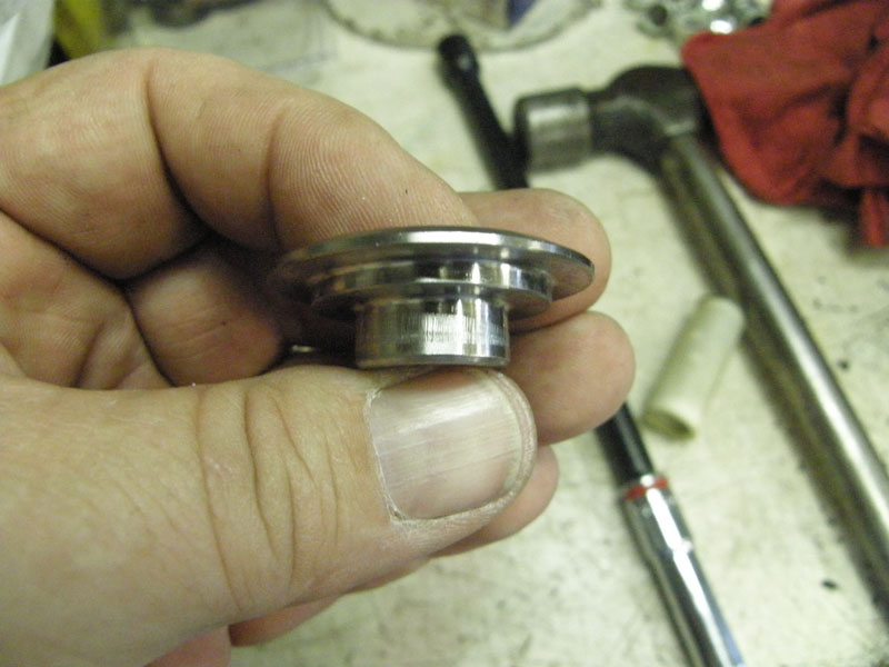
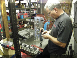
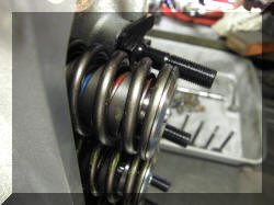
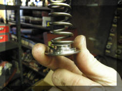
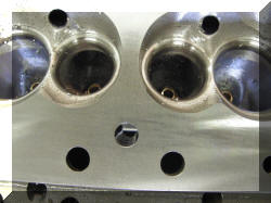
The fifth aftermarket fitment problem was the
valve spring retainers and the inner springs. Even with the springs
installed and 150 foot pounds of pressure of close valve spring
pressure the inner springs did not slip down over the retainers.
This was really a shame as I paid a lot of money for the titanium
valve spring retainers. |
 |
 |
 |
 |
|
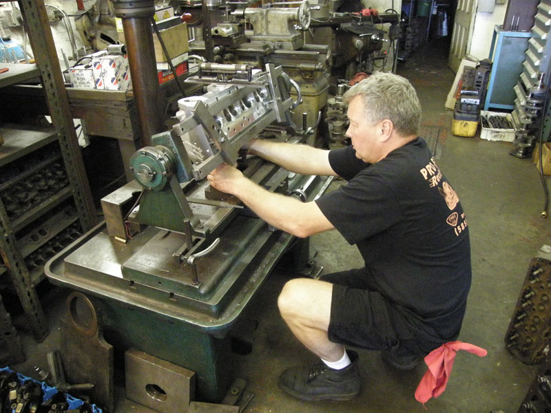
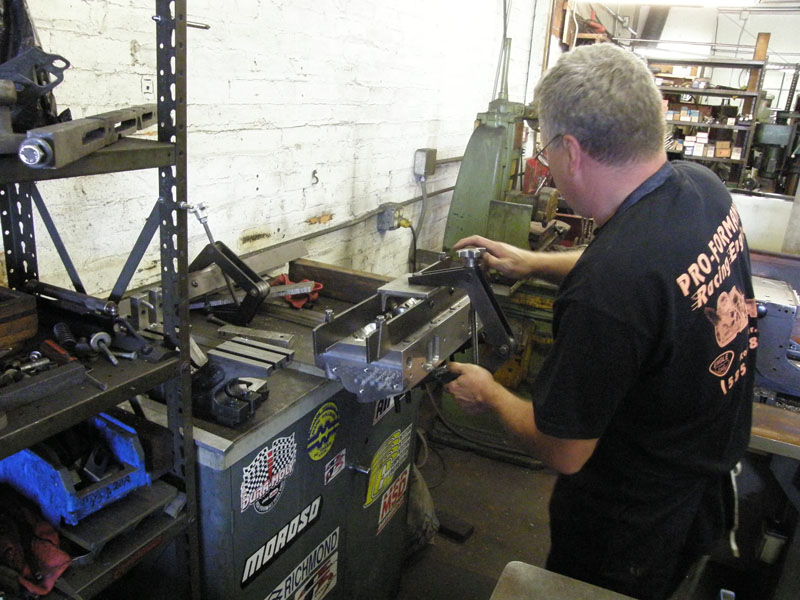
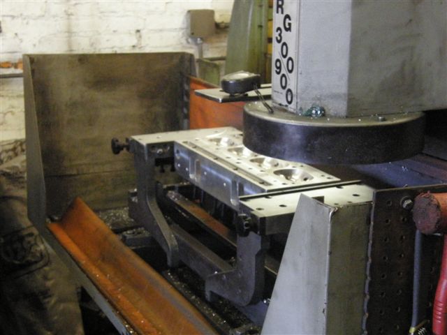
As time is really beginning to pass, and the
summer here is short, we just went out and bought a complete set of
new valve springs, retainers, and seats. The vendor has agreed to
take these back. Now that we are done
making metal chips with the heads it is time to get them smooth. The
first step is to attach the fixture that will set the milling
machine up square to the head. |
 |
 |
|
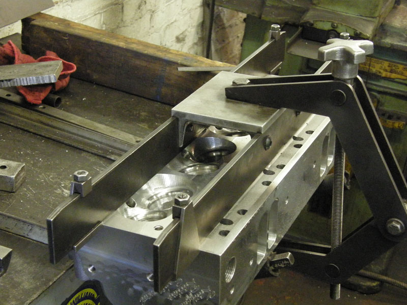
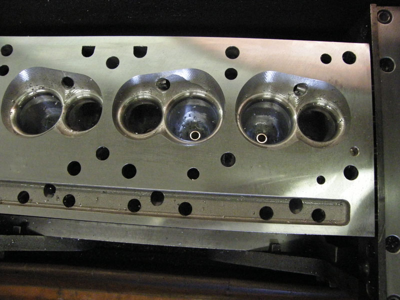
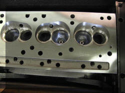
Note the step in the head caused by two passes
of the CNC machine that made these heads, and the welded up blind
holes. |
 |
 |
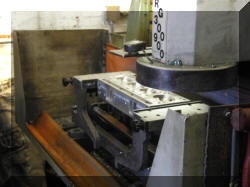 |
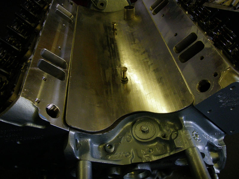
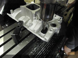
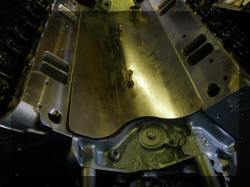
This is the decking machine, note the
difference in the surface of the heads below after decking. |
 |
 |
|
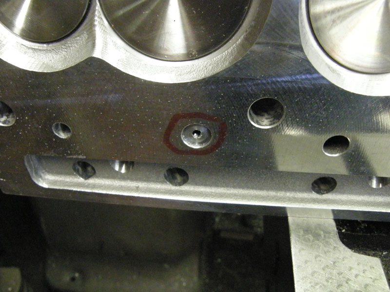
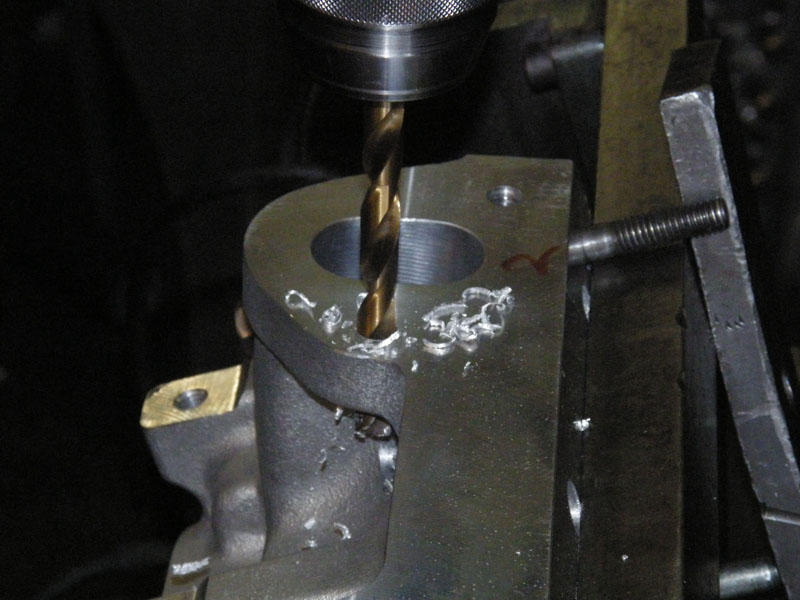
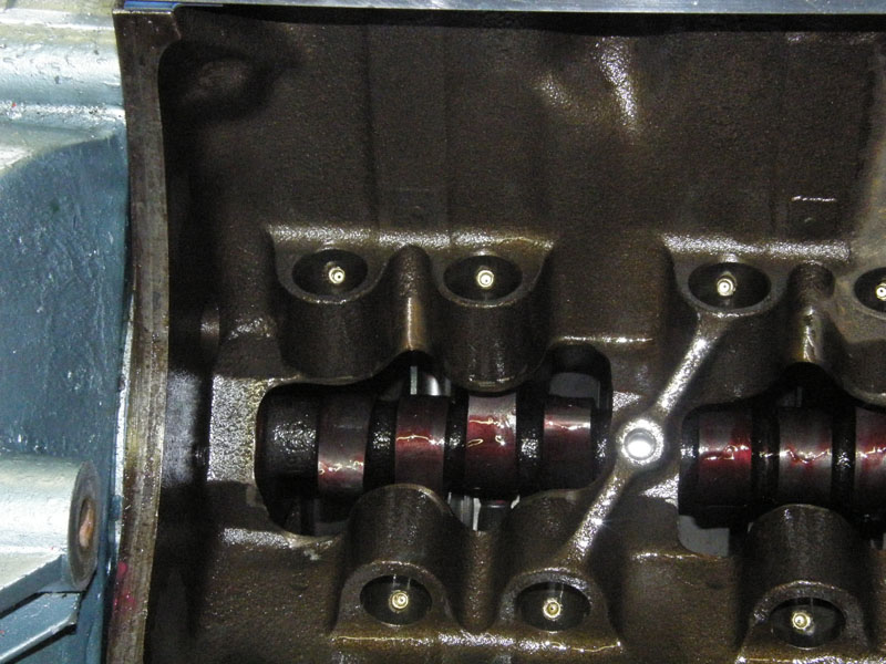
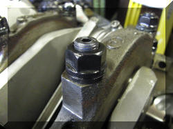
We have restricted the oil flow from the
lifters to the rocker arms to provide higher and more consistent
pressure for the rod and main bearings. This was done by drilling,
tapping, and inserting plugs in the lifter bores that were drilled
with a .042 hole. These plugs were purchased as a kit from Kauffman
Racing Equipment |
 |
 |
 |
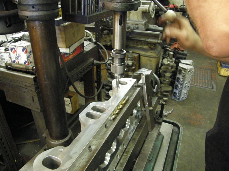
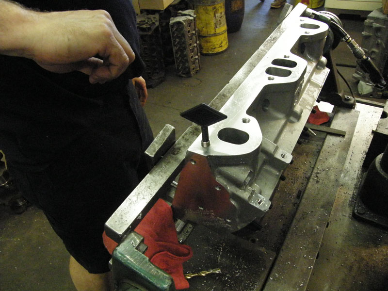
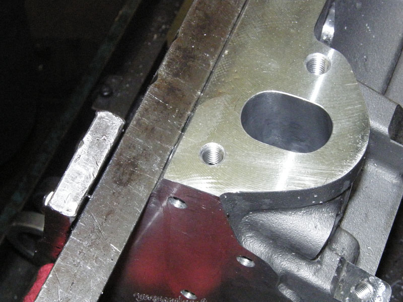
The sixth aftermarket part not to fit was the intake. The area that
is cut out for the PCV valve did not line up with the mount for the
PCV valve on the aftermarket valley pan. |
|
The seventh aftermarket part not to fit this
week was the valley pan. the front fit fine, but the back was way
off. |
 |
 |
|
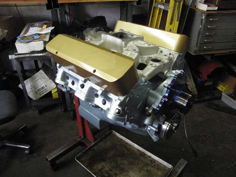
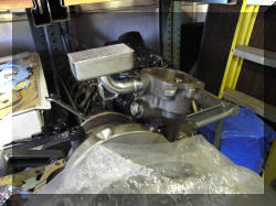
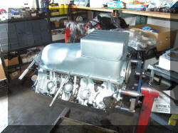
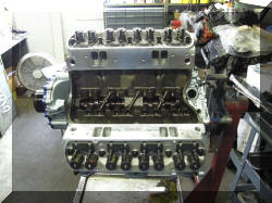
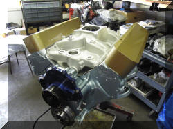
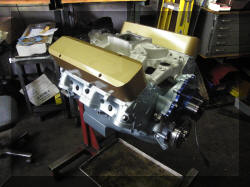
So to make myself feel better as to where we
are, we set the intake in place, and the valve covers in place just to
see what it would look like. |
 |
 |