|
REMEMBER TO CLICK PICTURES FOR MORE DETAIL /
LARGER PICTURE
|
|
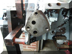
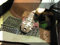
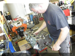
Jim Hand's book (if you do not have this
book, buy it) For high-RPM operation, especially with solid-lifter
cams, added oil flow from enlarging the passageway from the pump to
the oil filter may improve durability. We have done this and gone
ahead and taped the hole with 1/2 inch pipe threads so that AN
fittings can be screwed directly into the block for an external oil
filter. I will be installing a System One set up. Note. when you
remove the oil filter adapter you are also removing the oil filter
bypass valve. |
 |
 |
|
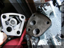
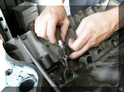
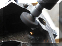
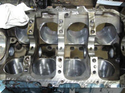
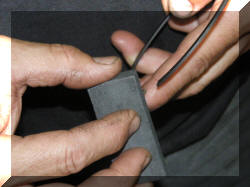
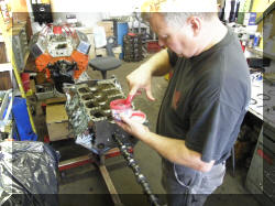
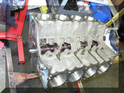
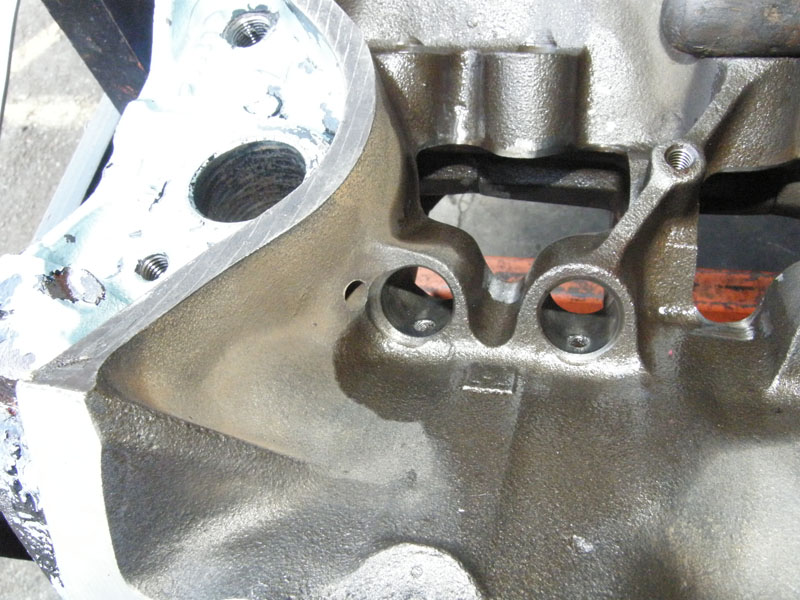
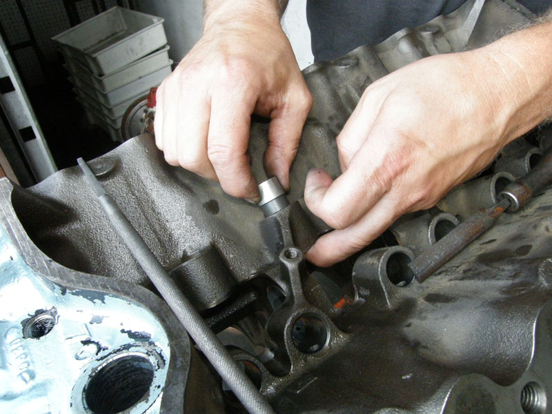
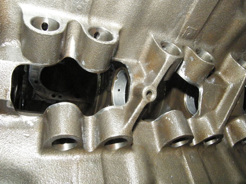
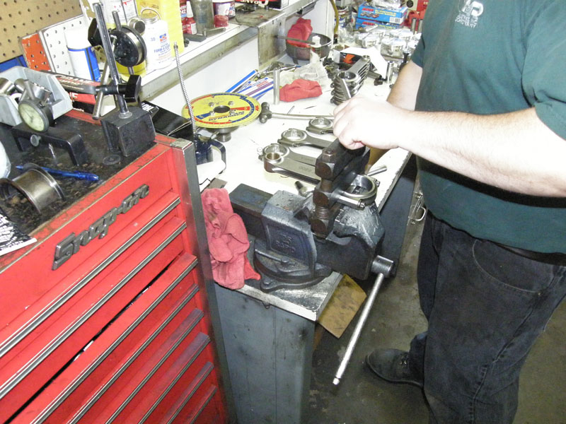
Jim Hand goes on to say restricting oil flow
from the lifters top the rockers provides higher and more consistent
pressure for rod and main bearings. The restriction can be
accomplished by drilling, tapping and installing drilled
stainless-steel plugs into the lifter bores. A .030 inch hole in the
plugs provides adequate flow to the rockers/springs while raising
pressure for the bearings. Jeff of Kaufman Racing sells the plugs.
He recommender .046 inch hole for my solid lifter cam. Below you see
the holes tapped, the rough edges smoothed out, and the lifter hole
check for smooth operation |
 |
 |
 |
 |
|
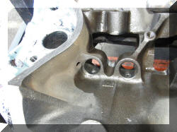
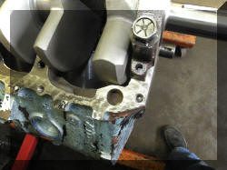
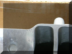
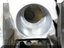
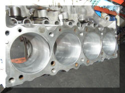
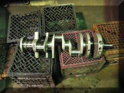
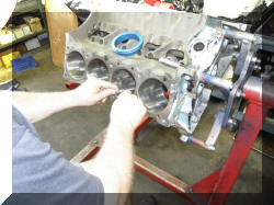
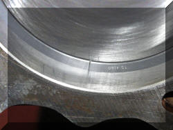
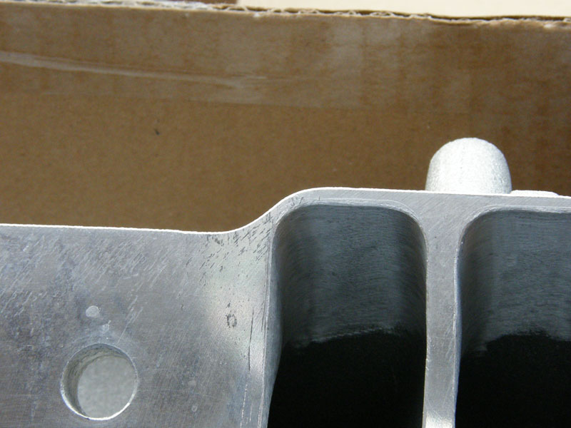
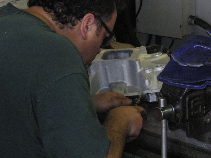
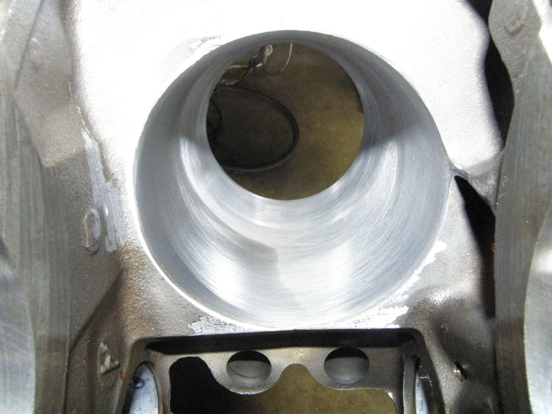
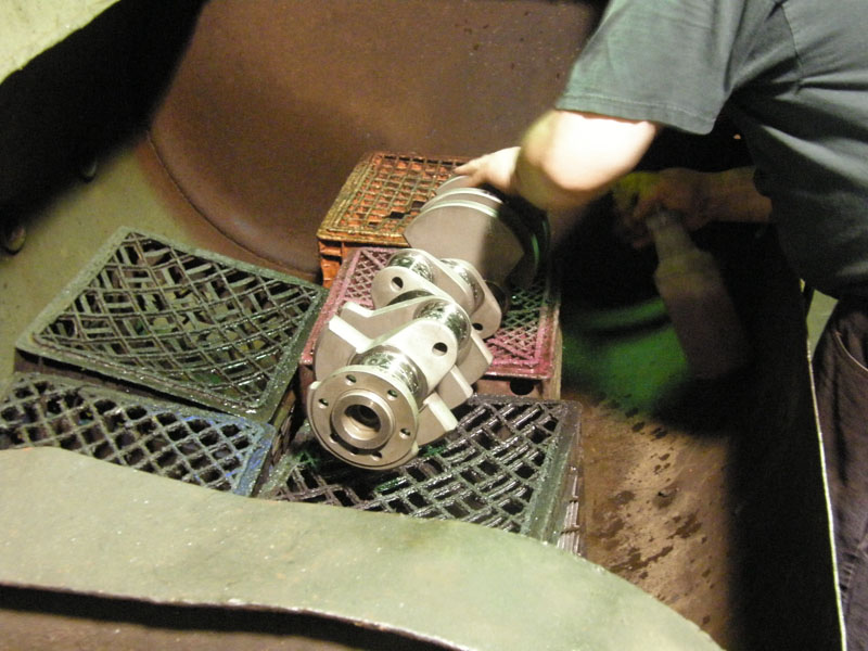
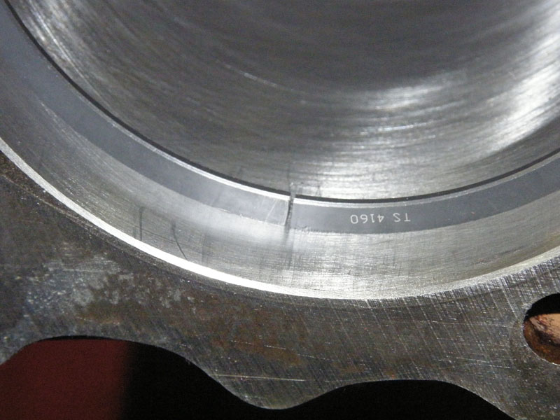
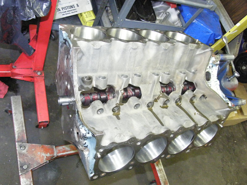
The stroker crank wa check for clearance. Only
the right front of the block need to be addressed. |
 |
 |
 |
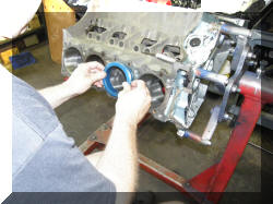
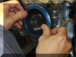
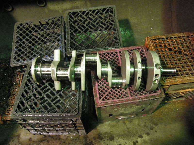
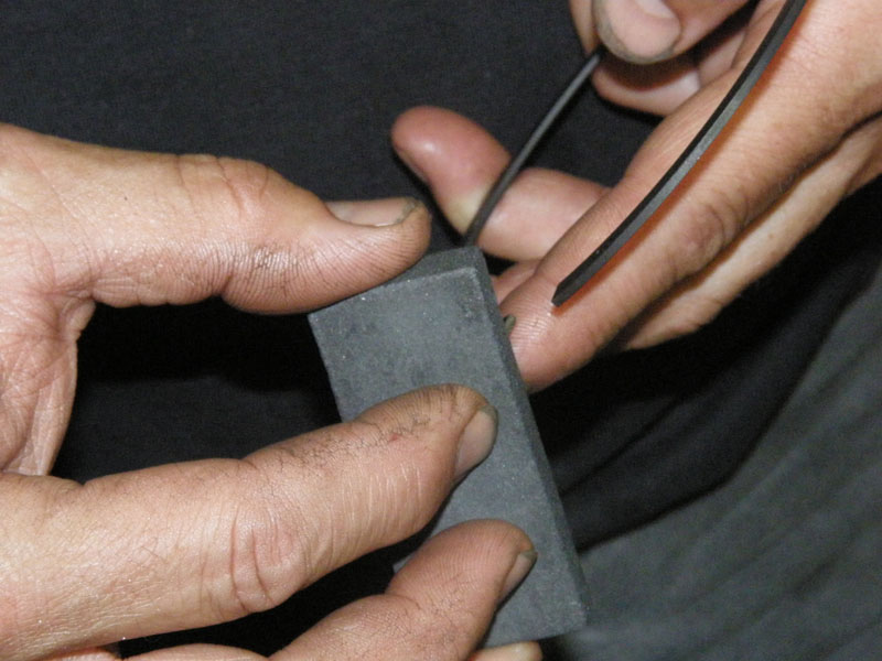
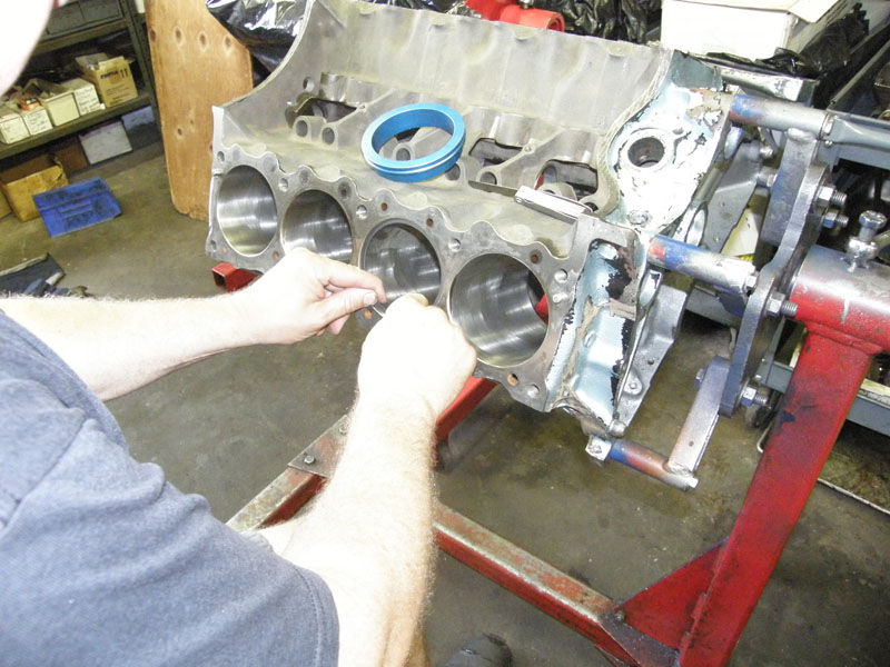
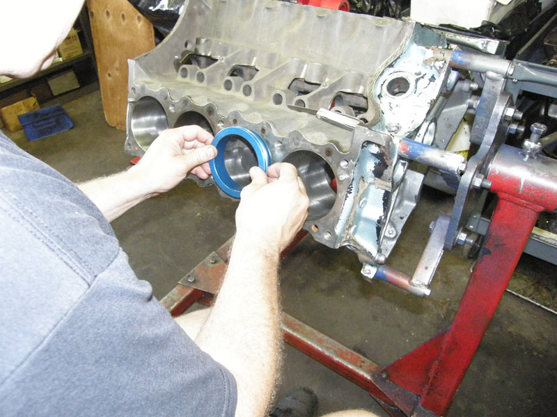
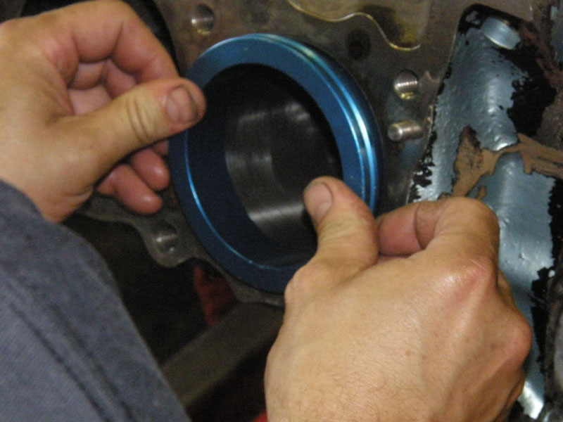
Later in the install we found another issue
with the oil separator ring at the rear of the crank, and an rear
main seal issue. Those will be addressed in next weeks update. |
|
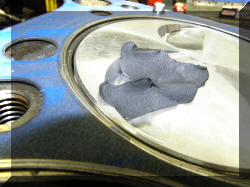
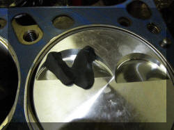
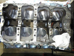
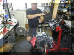
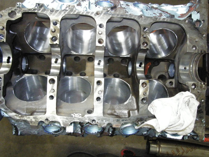
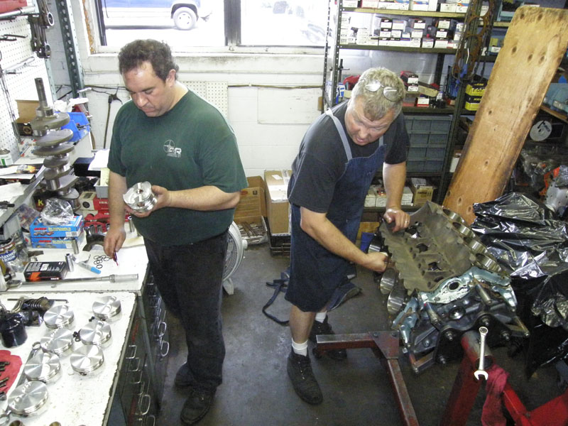
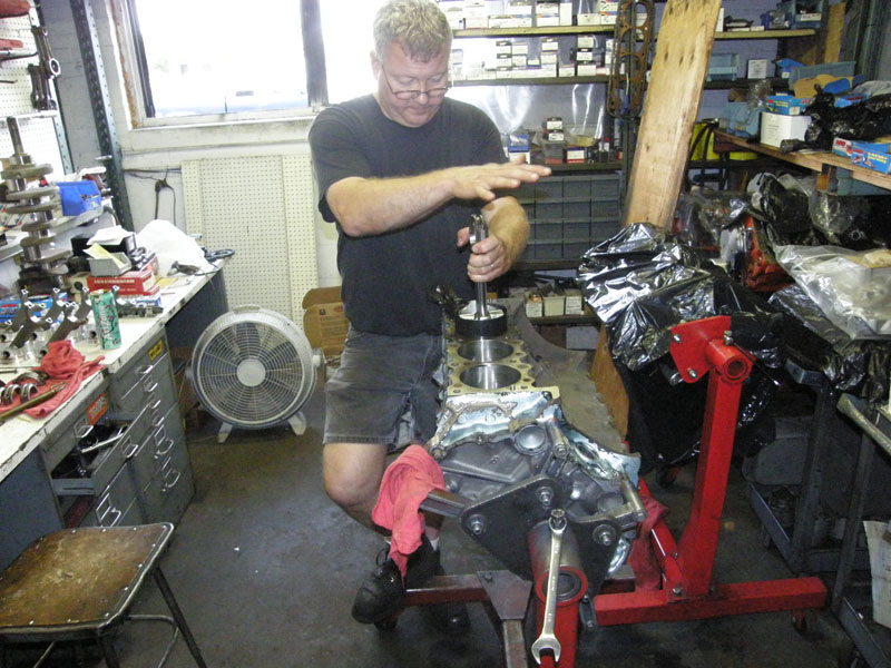
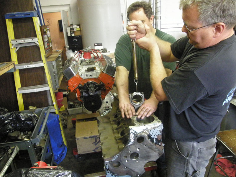
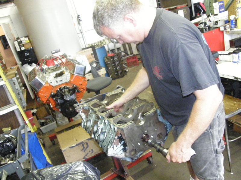
First step mock things together, and check
valve to Piston clearance. Turns out there is LOTS of room. If you
look closely you will see the depression in the clay on the tops of
the pistons made by the valves.. |
 |
 |
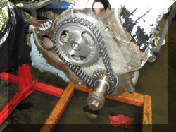 |
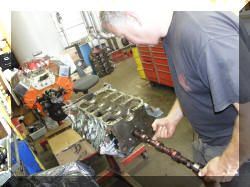
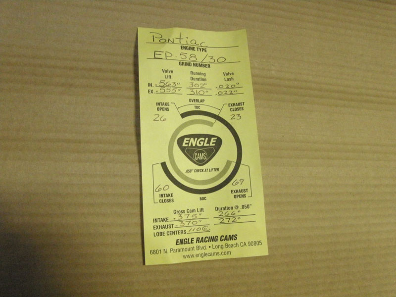
Cam was dialed in at one degree advance to
obtain 106 intake lobe center line.
On the
Pontiac engine that I am building I was told that I want
the intake lobe centerline of the cam to be 106 degrees after
TDC.
That was
Greek to me.
I had to
educate myself so with the help of Matt Shaft, Jeff Kaufman, and
Jim Hand’s Book, this is what I found and I thought someone else
might also find it interesting.
The cam card can be seen here.
This is
what I learned;
Intake opens before TDC
26 degrees
TDC to BDC
180 degrees
Intake closes after BDC
60 degrees
Total 266 degrees
divide by 2 to get centerline
with the Intake opening before
TDC 26
degrees 133 degrees
minus 26 (Intake opening before
TDC 26 degrees) as centerline
is referenced from TDC 107
degrees
If the cam is 1 degree advanced,
the camshaft is at
106 degrees centerline
|
|
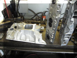
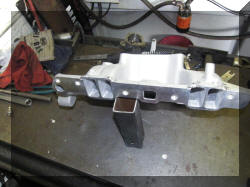
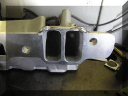
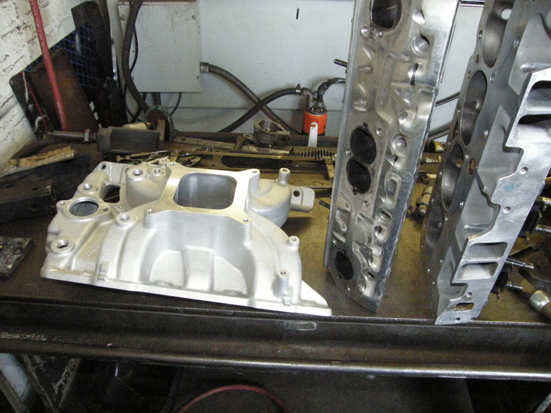
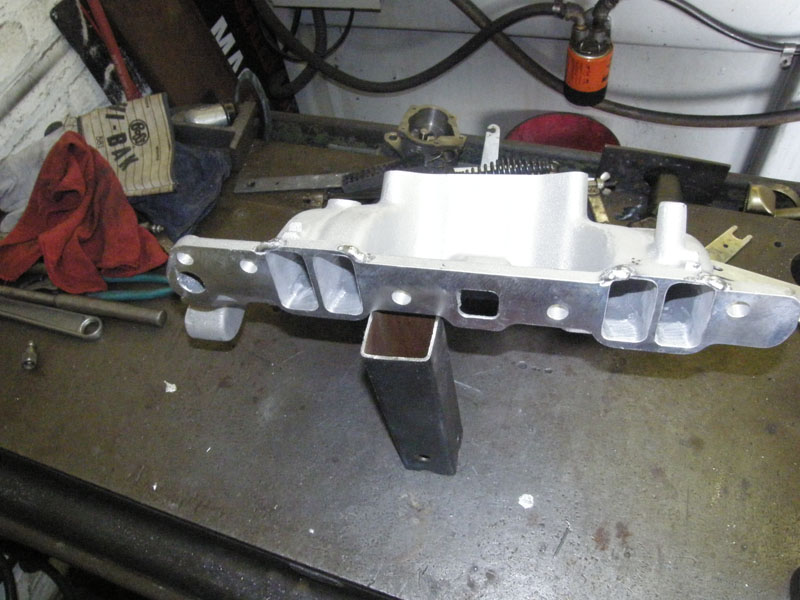
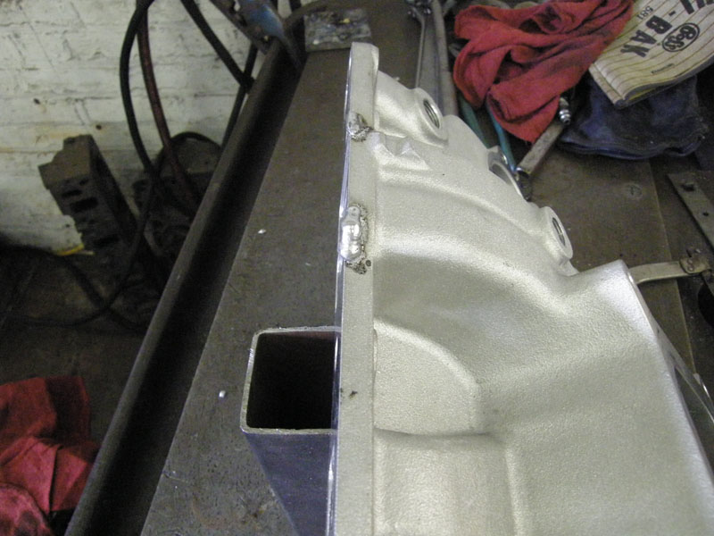
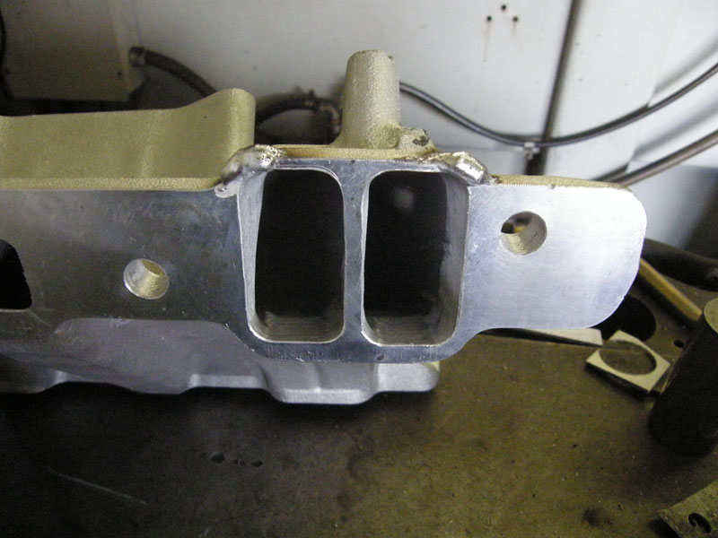
A side project was the intake. The intake was
port matched, but then the walls were to thin to get a good seal
between them and the heads, so material was added to thicken the
walls back up. |
 |
 |
 |
 |
 |
 |
|
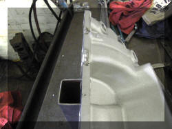
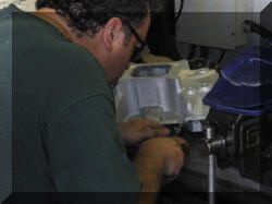
Work was not completed at the time of putting
this together, the finished intake will be pictured in next weeks
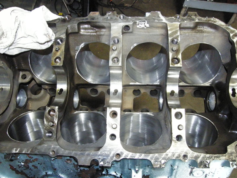
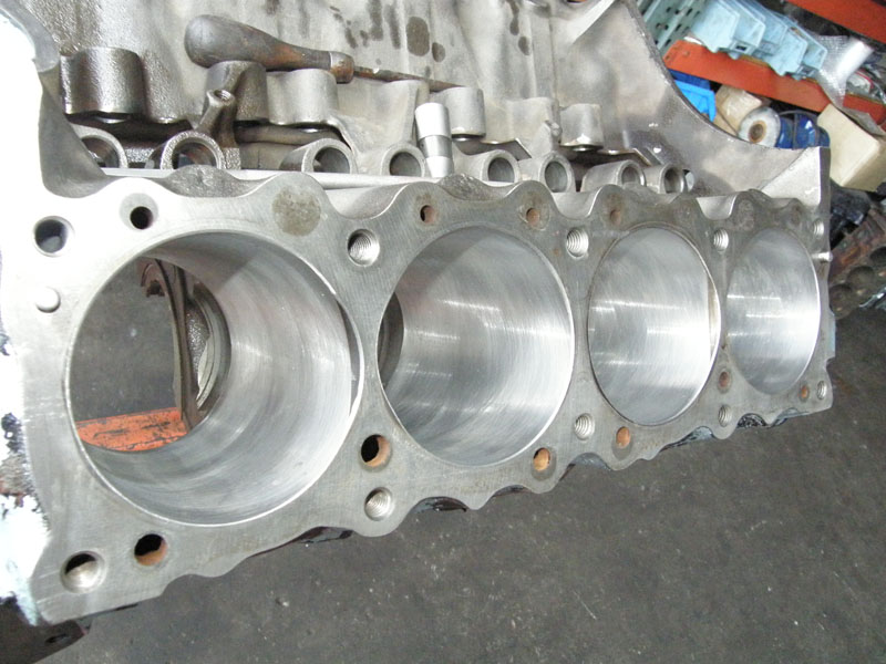
update. Next is to smooth out the
inside of the block |
 |
 |
 |
 |
 |
|
|
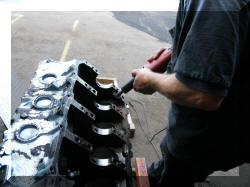
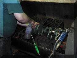
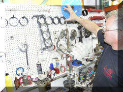
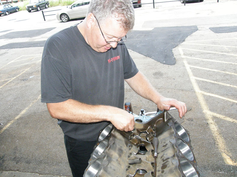
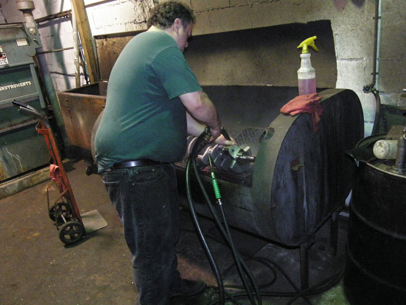
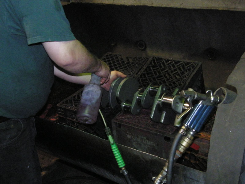
Block was then thoughly cleaned, Brushes were
used to clean all orifices, as was the crank. |
 |
 |
 |
 |
|
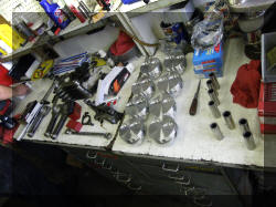
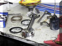
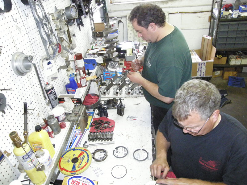
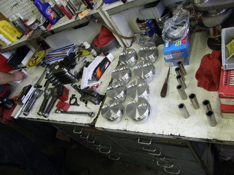
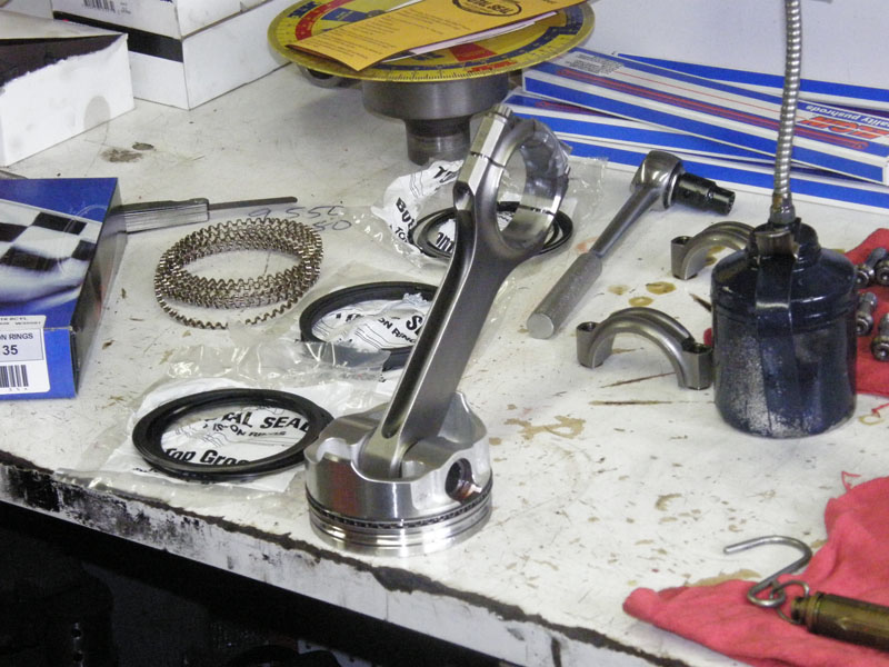
Time to set the pistons up. |
 |
 |
 |
 |
|
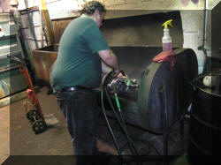
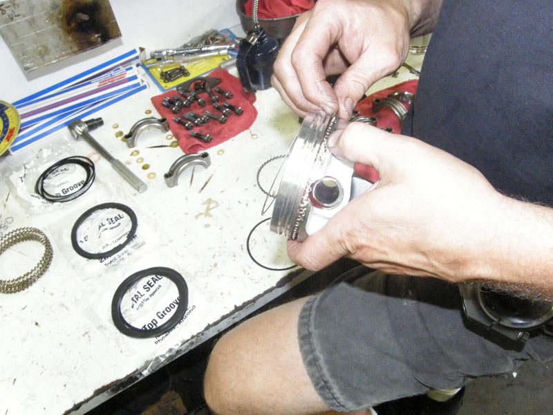
Time to file fit the rings. |
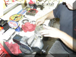 |
Use a diamond wheel to trim the length of the
ring |
|
File the edges smooth |
 |
 |
 |
Insert the ring into the cylinder, use the
tool below to square the ring in the cylinder and check the gap with
a feller gauge |
 |
 |
 |
Looks good. |
|
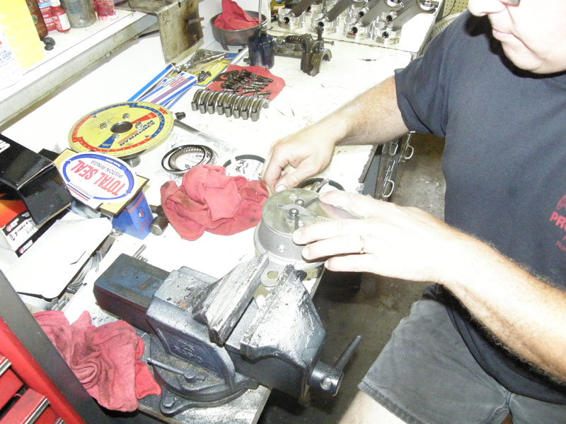
Next step was oil scraper ring tension. The
expander rings sent with the pistons were standard tension rings
(high tension) As this is a strictly race engine we decided to
reduce the tension from 35 pounds per cylinder to 20. We found that
using an expander ring set for a .60 over 396 engine that we got
down to the 20 pounds per cylinder. High end race engines try for o
pounds. They use a vacuum pump mounted on the front of the engine to
create a vacuum inside the engine block to suck the oil back in
through the holes in the piston |
 |
 |
 |
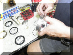
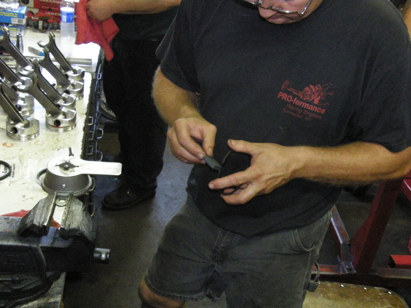
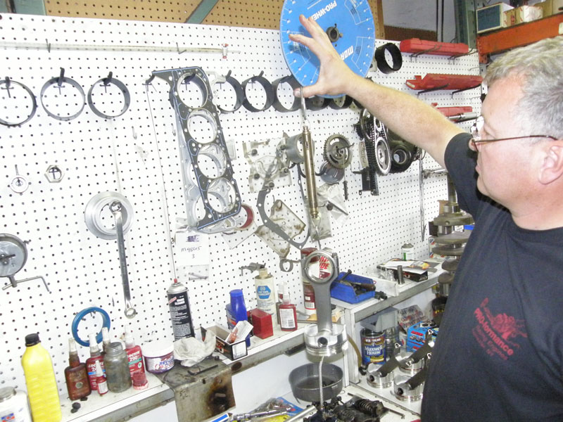
Weight the piston so that weight can be subtracted when you
test for pressure required to move the piston with a given set of
expander rings. |
 |
Install the piston in the block with just the oil rings and
expander. |
 |
Use you handy dandy fish scale to find the amount of pressure to
pull the piston out of the block and subtract the weight of the
piston and you have the oil ring tension. Make sure you have someone
cover the hole so that the ring does not come shooting out of the
cylinder when you reach the "breaking point. |
|
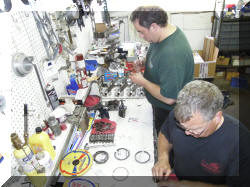
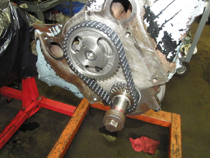
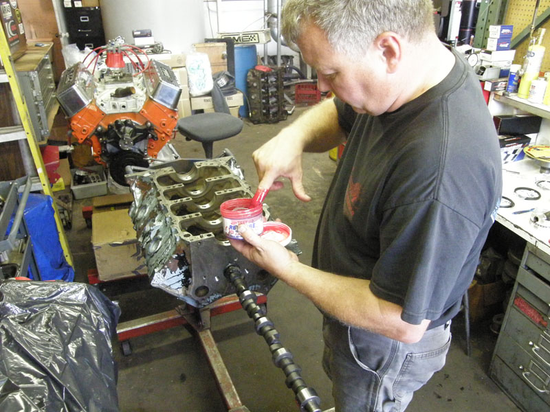
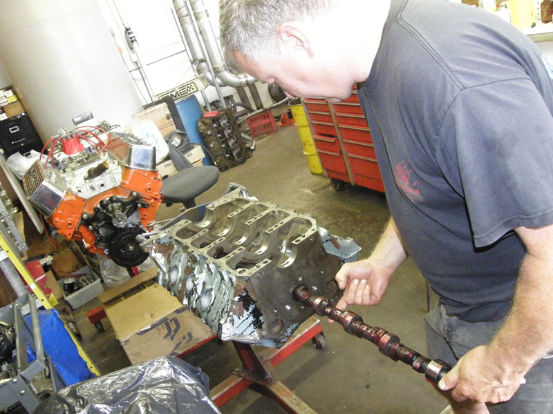
Now we can start putting stuff in for good. We
will start with the cam, which will be degreed again. |
 |
 |
 |
 |


