Now on
to the rear cross member fabrication and the location of
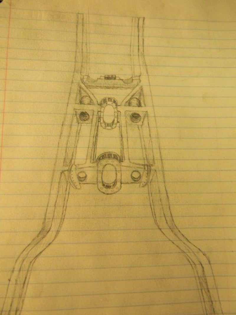
the rear axle with a four link system and track bar.
This is new to me and I had to sit
down and draw it out. I want provisions to run an
exhaust system should this vehicle ever want to end up
on the street. It needs to be really strong as it holds
the rear end in place and we will be pushing 500 HP, and
we want to plant the HP to the ground so the geometry
has to be right.
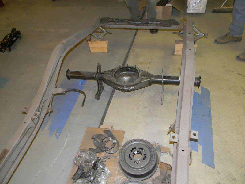
Now I get to move on to the rear
end! Lots to do here.
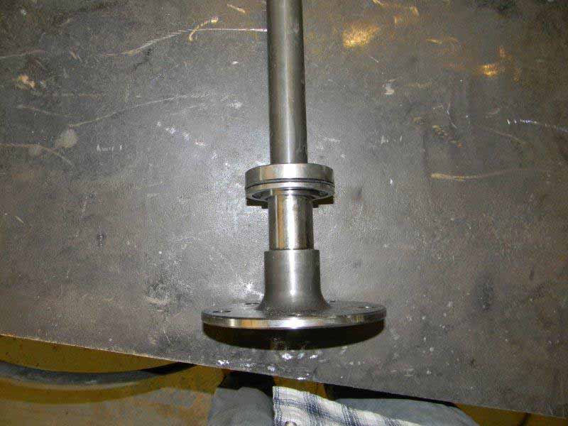
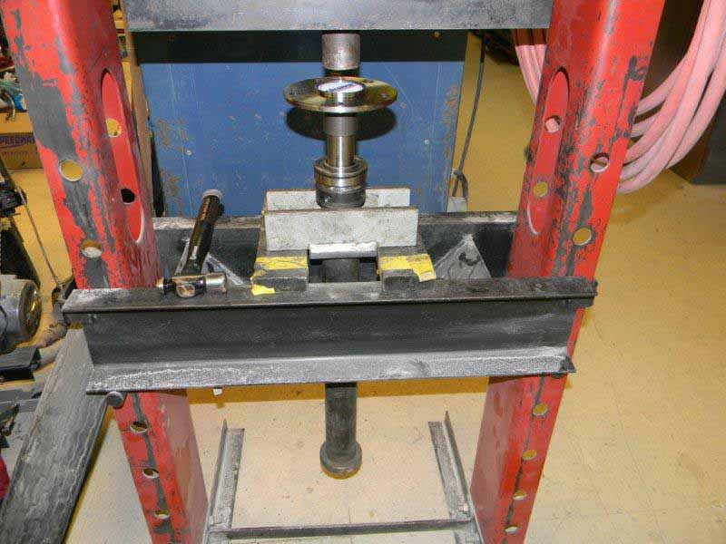
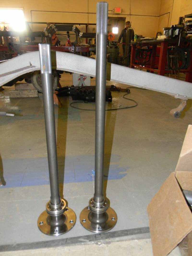
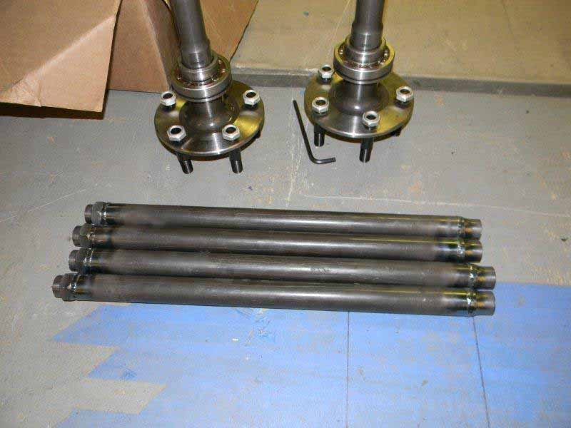
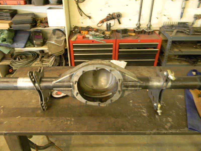
To get started I pressed the
bearings onto the axle shafts and bolted them into the
differential. As we did not know what gears to order
(will wait on the dyno runs for HP), I created a slip[
tube to hold the insides of the axles in the correct
location
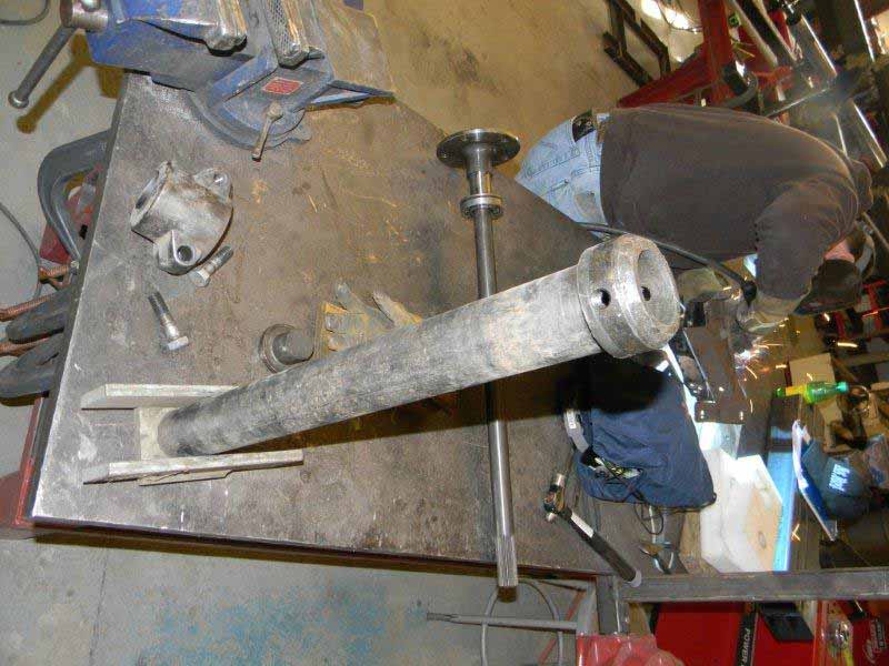
With the bearings pressed onto the
axle shafts the next task was to weld up the bungs for
the four link bars
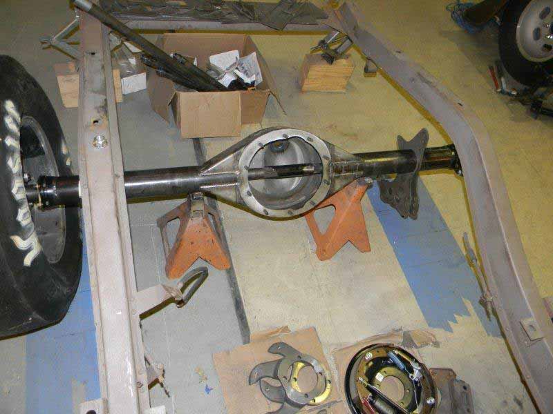
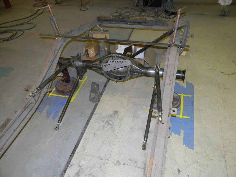
Now that we know the drop angle of
the engine we know the proper angle of the pinion and
the four link brackets can be welded to the axle tube.
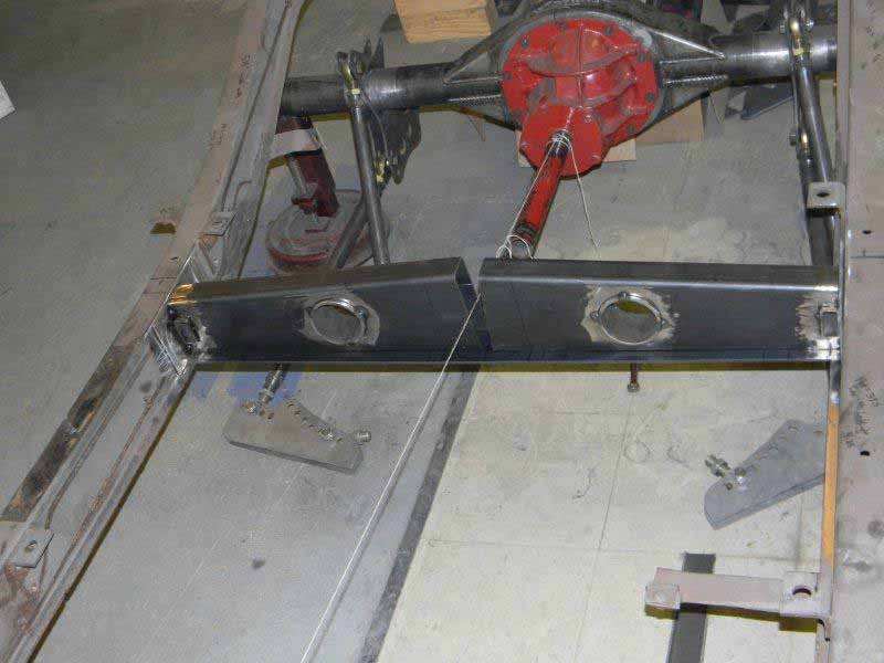
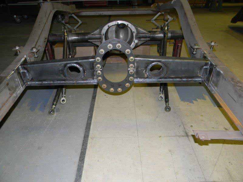
With the four link bars attached
to the rear end it is obvious that we need something to
attach them to.
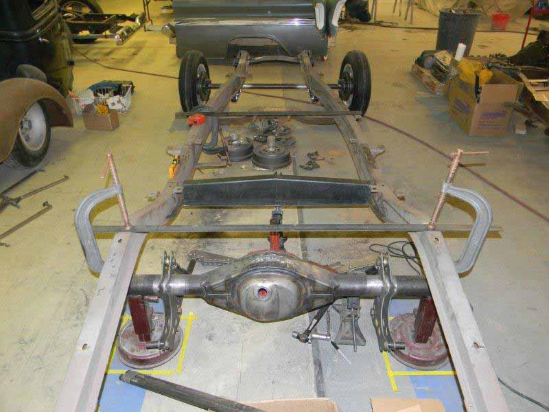
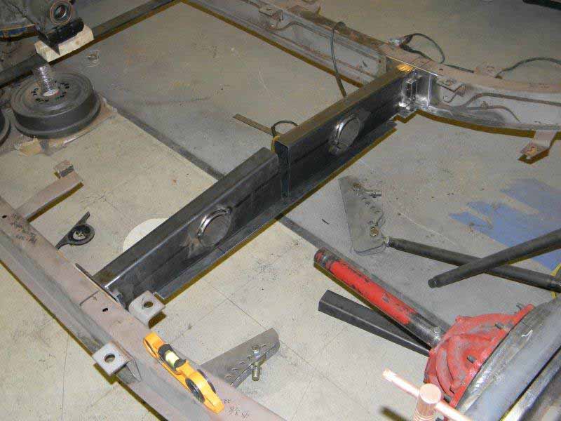
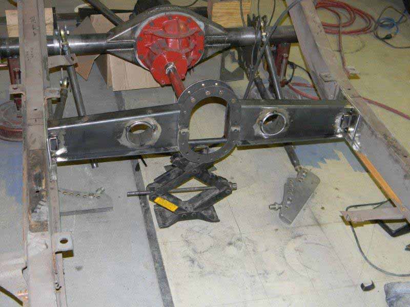
So the start of the cross member
can be seen. With a mock up fifth member in place and
the mock up engine in place I can string a string to
find the location of the drive shaft. Note the holes in
the cross member for a future exhaust system.
You are now up to date.
Please remember that I am
looking for a good hot rod fabrication shop to call home
Ok, I have all the pieces and have
lined everything back up to start putting them together
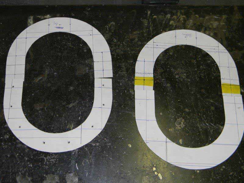
I made
some templates for the driveshaft loop in the rear
crossmember and cut out the steel
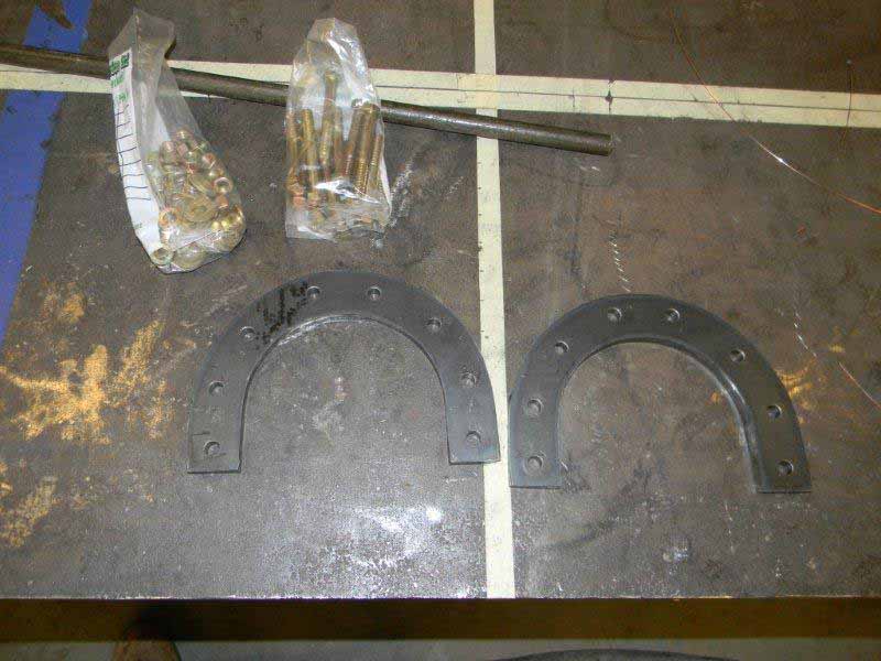
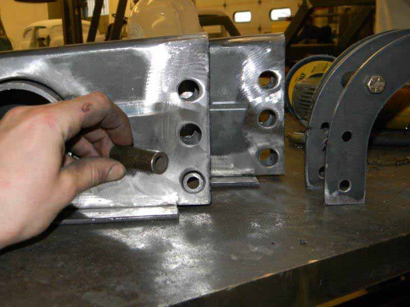
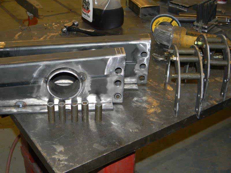
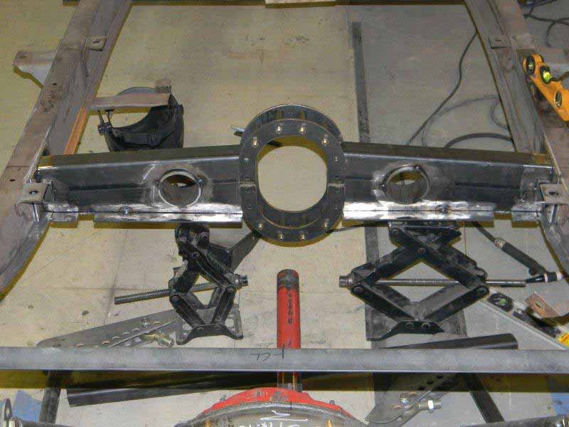
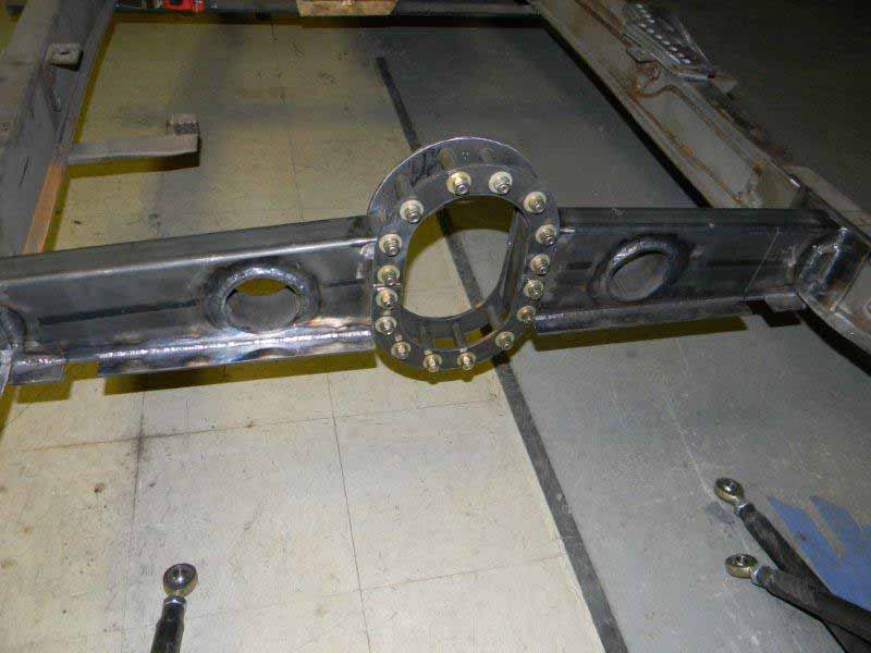
Cut the holes in the cross member
for the sleeves cut to stop the cross member from being
crushed when the bolts are tightened.
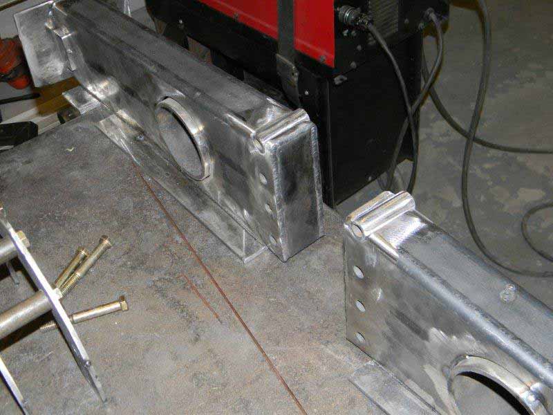
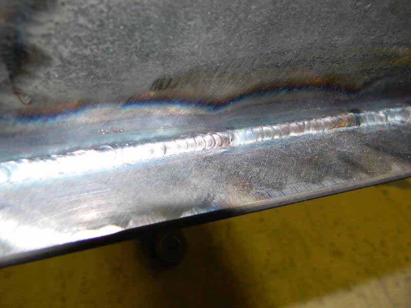
Welded the sleeves in
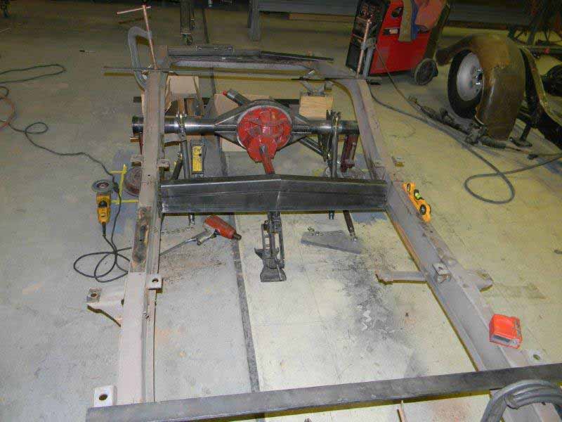
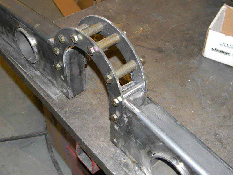
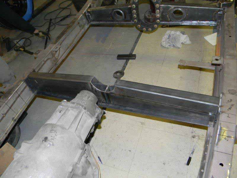
The assembly starts. The top half
will be welded together, the bottom half will remain
bolted so that the driveshaft can be removed
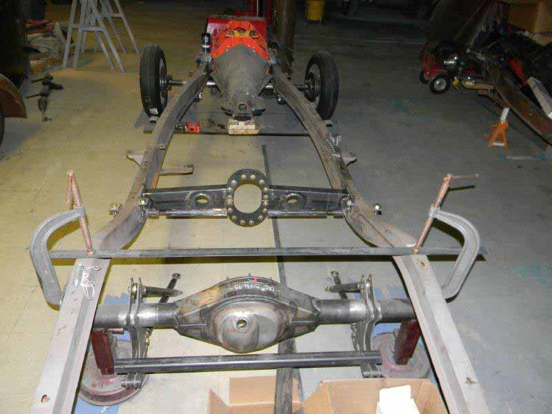
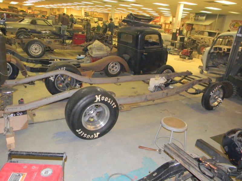
Crossmember installed in the chassis, both a front and
rear view.